Page 1 of 1
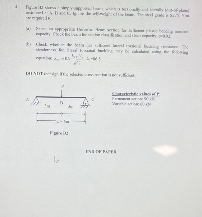
4 Figure B2 shows a simply supported beam, which is torsionally and laterally (out-of-plane) restrained at A, B and C. I
Posted: Mon May 16, 2022 8:37 am
by answerhappygod
- 4 Figure B2 Shows A Simply Supported Beam Which Is Torsionally And Laterally Out Of Plane Restrained At A B And C I 1 (39.11 KiB) Viewed 93 times
4 Figure B2 shows a simply supported beam, which is torsionally and laterally (out-of-plane) restrained at A, B and C. Ignore the self-weight of the beam. The steel grade is $275. You are required to: (a) Select an appropriate Universal Beam section for sufficient plastic bending moment capacity. Check the beam for section classification and shear capacity. <=0.92 (b) Check whether the beam has sufficient lateral torsional buckling resistance. The slenderness for lateral torsional buckling may be calculated using the following equation: Any = 0.91,7/12=86.8. va DO NOT redesign if the selected cross-section is not sufficient. P Characteristic values of P: Permanent action: 90 KN Variable action: 60 KN 3m B 3m *** L = 6m Figure B2 END OF PAPER