Page 1 of 1
1. A typical floor plan view is shown in Figure 1. Design the longitudinal reinforcement and shear reinforcement for the
Posted: Mon May 16, 2022 7:18 am
by answerhappygod

- 1 A Typical Floor Plan View Is Shown In Figure 1 Design The Longitudinal Reinforcement And Shear Reinforcement For The 1 (42.51 KiB) Viewed 56 times
- 1 A Typical Floor Plan View Is Shown In Figure 1 Design The Longitudinal Reinforcement And Shear Reinforcement For The 2 (42.51 KiB) Viewed 56 times
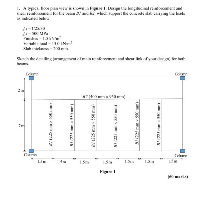
1. A typical floor plan view is shown in Figure 1. Design the longitudinal reinforcement and shear reinforcement for the beam Bl and B2, which support the concrete slab carrying the loads as indicated below: fck=C25/30 fox = 500 MPa Finishes = 1.5 kN/m² Variable load = 15.0 kN/m² Slab thickness = 200 mm Sketch the detailing (arrangement of main reinforcement and shear link of your design) for both beams. Column Column 2 m B2 (400 mm x 950 mm) 7m BI (225 mm x 550 mm) BI (225 mm x 550 mm) | BI (225 mm x 550 mm) BI (225 mm x 550 mm) BI (225 mm x 550 mm) BI (225 mm x 550 mm) Column 1.5 m Column 1.5m 1.5m 1.5m 1.5m 1.5 m 1.5m Figure 1 (60 marks)