Page 1 of 1
A four-bar linkage with an open configuration is shown in Figure 1. The relevant data for the linkage is provided in Tab
Posted: Mon May 16, 2022 6:50 am
by answerhappygod
- A Four Bar Linkage With An Open Configuration Is Shown In Figure 1 The Relevant Data For The Linkage Is Provided In Tab 1 (98.81 KiB) Viewed 65 times
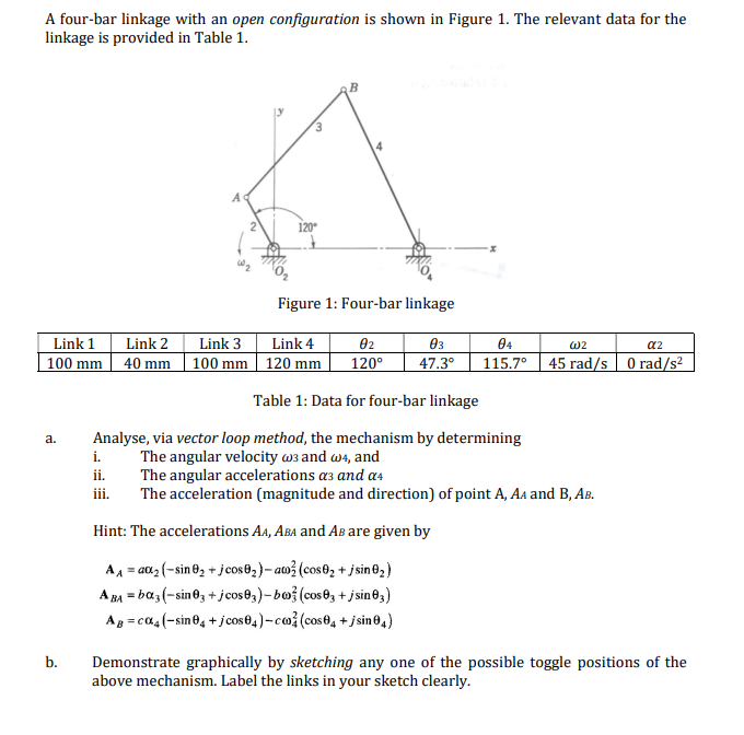
A four-bar linkage with an open configuration is shown in Figure 1. The relevant data for the linkage is provided in Table 1. 120° Figure 1: Four-bar linkage Link 1 100 mm Link 2 40 mm Link 3 Link 4 100 mm | 120 mm 02 120° 03 47.3° 04 115.7° W2 a2 45 rad/s 0 rad/s2 Table 1: Data for four-bar linkage a. Analyse, via vector loop method, the mechanism by determining i. The angular velocity w3 and w4, and ii. The angular accelerations a3 and a4 iii. The acceleration (magnitude and direction) of point A, AA and B, AB. Hint: The accelerations AA, ABA and AB are given by A = 202 (-sin 02 + jcos0z)-au (cos8, +jsin ºz) A BA = baz (-sin 03 + jcos63)-boz (cos03 +jsin 63) Ag=cQu(-sin 0, + jcos 64) -co (cos 64 + jsin04) b. Demonstrate graphically by sketching any one of the possible toggle positions of the above mechanism. Label the links in your sketch clearly.