Page 1 of 1
Synthesis and Analysis of a Quick Return Crank Slider Mechanism 50mm A 3 b B' B 01 a e d4 Figure 1 A Crank Slider Mechan
Posted: Mon May 16, 2022 6:43 am
by answerhappygod
- Synthesis And Analysis Of A Quick Return Crank Slider Mechanism 50mm A 3 B B B 01 A E D4 Figure 1 A Crank Slider Mechan 1 (215.49 KiB) Viewed 45 times
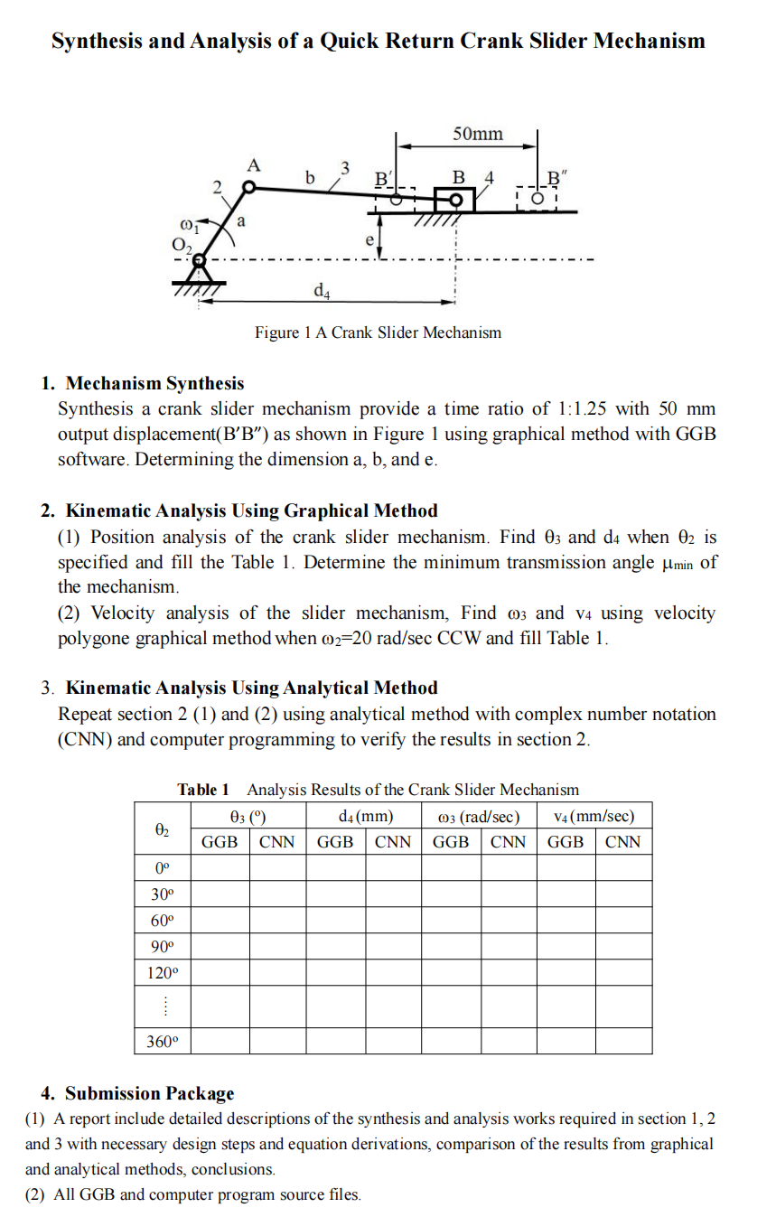
Synthesis and Analysis of a Quick Return Crank Slider Mechanism 50mm A 3 b B' B 01 a e d4 Figure 1 A Crank Slider Mechanism 1. Mechanism Synthesis Synthesis a crank slider mechanism provide a time ratio of 1:1.25 with 50 mm output displacement(B'B”) as shown in Figure 1 using graphical method with GGB software. Determining the dimension a, b, and e. 2. Kinematic Analysis Using Graphical Method (1) Position analysis of the crank slider mechanism. Find 03 and d4 when 02 is specified and fill the Table 1. Determine the minimum transmission angle umin of the mechanism. (2) Velocity analysis of the slider mechanism, Find 03 and v4 using velocity polygone graphical method when 02=20 rad/sec CCW and fill Table 1. 3. Kinematic Analysis Using Analytical Method Repeat section 2 (1) and (2) using analytical method with complex number notation (CNN) and computer programming to verify the results in section 2. Table 1 Analysis Results of the Crank Slider Mechanism 03 0 d4 (mm) 03 (rad/sec) V4(mm/sec) GGB CNN GGB CNN GGB CNN GGB CNN 02 0° 30° 600 90° 1200 360° 4. Submission Package (1) A report include detailed descriptions of the synthesis and analysis works required in section 1, 2 and 3 with necessary design steps and equation derivations, comparison of the results from graphical and analytical methods, conclusions, (2) All GGB and computer program source files.