Page 1 of 1
A gear train as shown in Figure QA5 is designed for a driving system of an automatic guided vehicle. A 16-tooth gear A m
Posted: Mon May 16, 2022 6:21 am
by answerhappygod
- A Gear Train As Shown In Figure Qa5 Is Designed For A Driving System Of An Automatic Guided Vehicle A 16 Tooth Gear A M 1 (148.8 KiB) Viewed 88 times
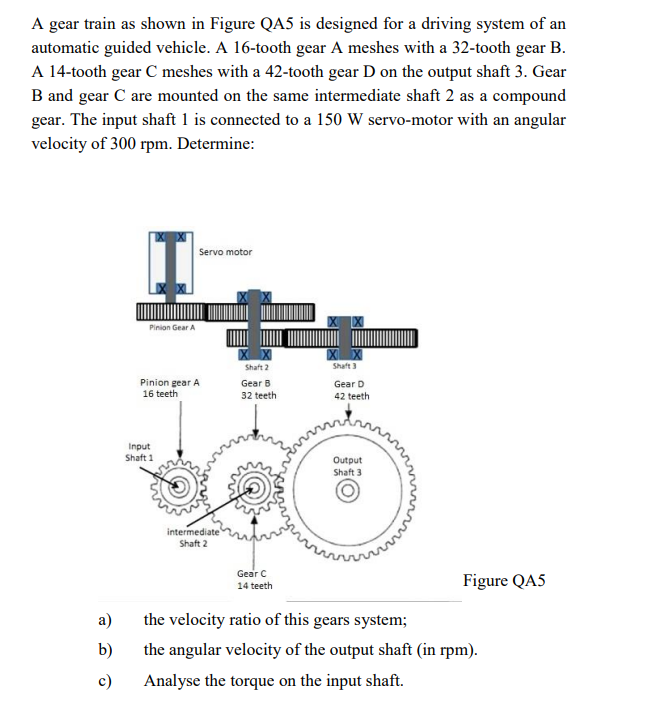
A gear train as shown in Figure QA5 is designed for a driving system of an automatic guided vehicle. A 16-tooth gear A meshes with a 32-tooth gear B. A 14-tooth gear C meshes with a 42-tooth gear D on the output shaft 3. Gear B and gear C are mounted on the same intermediate shaft 2 as a compound gear. The input shaft 1 is connected to a 150 W servo-motor with an angular velocity of 300 rpm. Determine: Servo motor I Pinion Gear A X X Pinion gear A 16 teeth XX Shaft 2 Gear B 32 teeth XX Shaft 3 Gear D 42 teeth enarra Input Shaft 1 Output Shaft 3 intermediate Shaft 2 Gear 14 teeth Figure QA5 a) b) the velocity ratio of this gears system; the angular velocity of the output shaft (in rpm). Analyse the torque on the input shaft. c)