Page 1 of 1
Q2. The I beam Shown in Figure 2 is subjected to a point load of 100N at the middle (middle at the longitudinal section)
Posted: Sun May 15, 2022 10:47 pm
by answerhappygod
- Q2 The I Beam Shown In Figure 2 Is Subjected To A Point Load Of 100n At The Middle Middle At The Longitudinal Section 1 (29.1 KiB) Viewed 151 times
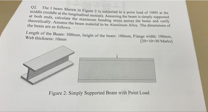
Q2. The I beam Shown in Figure 2 is subjected to a point load of 100N at the middle (middle at the longitudinal section). Assuming the beam is simply supported at both ends, calculate the maximum bending stress across the beam and verify theoretically. Assume the beam material to be Aluminum Alloy. The dimensions of the beam are as follows. Length of the Beam: 300mm, height of the beam: 100mm, Flange width: 100mm, Web thickness: 10mm [20+10-30 Marks) Figure 2: Simply Supported Beam with Point Load