Page 1 of 1
Q1. Figure I shows the triangular plate fixed at one end and the force F at the other end. Using the SolidWorks static a
Posted: Sun May 15, 2022 10:47 pm
by answerhappygod
- Q1 Figure I Shows The Triangular Plate Fixed At One End And The Force F At The Other End Using The Solidworks Static A 1 (39.85 KiB) Viewed 66 times
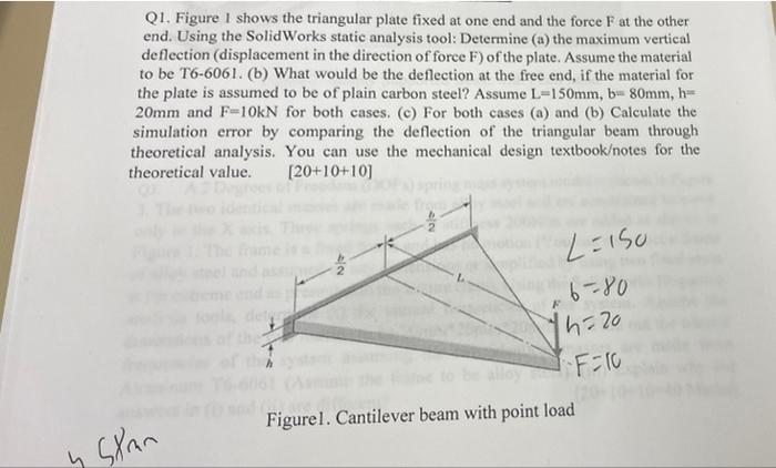
Q1. Figure I shows the triangular plate fixed at one end and the force F at the other end. Using the SolidWorks static analysis tool: Determine (a) the maximum vertical deflection (displacement in the direction of force F) of the plate. Assume the material to be T6-6061. (b) What would be the deflection at the free end, if the material for the plate is assumed to be of plain carbon steel? Assume L=150mm, b=80mm, h- 20mm and F-10kN for both cases. (c) For both cases (a) and (b) Calculate the simulation error by comparing the deflection of the triangular beam through theoretical analysis. You can use the mechanical design textbook/notes for the theoretical value. [20+10+10) N L=150 6-80 14-20 "F=10 Figurel. Cantilever beam with point load y Stran