Page 1 of 1
2. For the electromechanical model shown in Figure 2, do the following, Fixed field R L Armature circuit bé Rotor i. ii.
Posted: Sun May 15, 2022 9:37 pm
by answerhappygod
- 2 For The Electromechanical Model Shown In Figure 2 Do The Following Fixed Field R L Armature Circuit Be Rotor I Ii 1 (43.57 KiB) Viewed 51 times
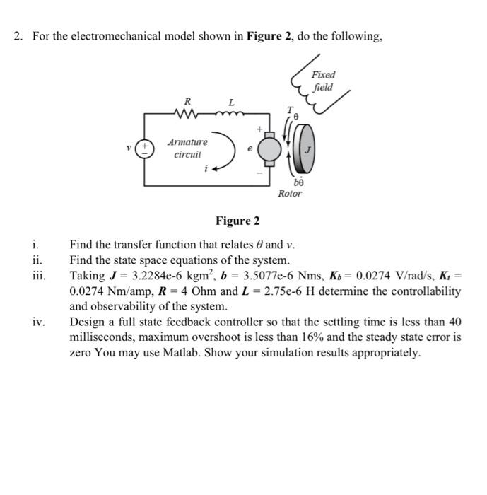
2. For the electromechanical model shown in Figure 2, do the following, Fixed field R L Armature circuit bé Rotor i. ii. Figure 2 Find the transfer function that relates 0 and v. Find the state space equations of the system. Taking J = 3.2284e-6 kgm , b = 3.5077e-6 Nms, Kb = 0.0274 V/rad/s, K. = 0.0274 Nm/amp, R = 4 Ohm and L = 2.75e-6 H determine the controllability and observability of the system. Design a full state feedback controller so that the settling time is less than 40 milliseconds, maximum overshoot is less than 16% and the steady state error is zero You may use Matlab. Show your simulation results appropriately. iv.