Page 1 of 1
5:48 PM Mon May 9 789% 3. (25%) Figure 4 shows a simplified schematic of the drive system of joint 4 of the PUMA 560. Th
Posted: Sun May 15, 2022 9:25 pm
by answerhappygod
- 5 48 Pm Mon May 9 789 3 25 Figure 4 Shows A Simplified Schematic Of The Drive System Of Joint 4 Of The Puma 560 Th 1 (53.8 KiB) Viewed 68 times
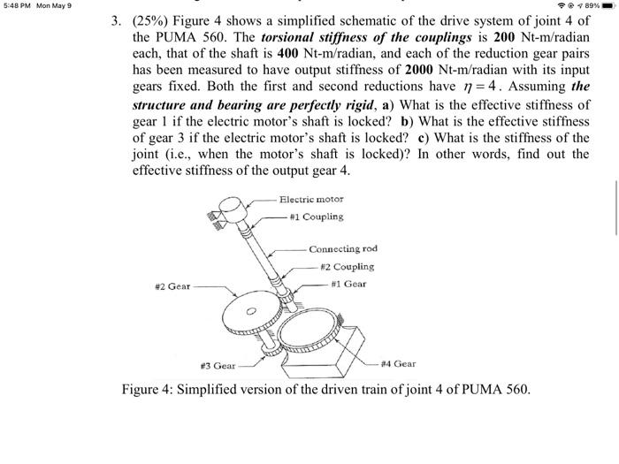
5:48 PM Mon May 9 789% 3. (25%) Figure 4 shows a simplified schematic of the drive system of joint 4 of the PUMA 560. The torsional stiffness of the couplings is 200 Nt-m/radian each, that of the shaft is 400 Nt-m/radian, and each of the reduction gear pairs has been measured to have output stiffness of 2000 Nt-m/radian with its input gears fixed. Both the first and second reductions have n = 4. Assuming the structure and bearing are perfectly rigid, a) What is the effective stiffness of gear 1 if the electric motor's shaft is locked? b) What is the effective stiffness of gear 3 if the electric motor's shaft is locked? c) What is the stiffness of the joint (i.e., when the motor's shaft is locked)? In other words, find out the effective stiffness of the output gear 4. Electric motor - #1 Coupling Connecting rod - #2 Coupling - #1 Gear #2 Gear 24 Gear #3 Gear Figure 4: Simplified version of the driven train of joint 4 of PUMA 560.