Page 1 of 1
Question 6: Finite Element Analysis [20 marks] Figure 26 illustrates the idealisation of a wing structure along with its
Posted: Sun May 15, 2022 9:23 pm
by answerhappygod
- Question 6 Finite Element Analysis 20 Marks Figure 26 Illustrates The Idealisation Of A Wing Structure Along With Its 1 (37.65 KiB) Viewed 32 times
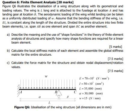
Question 6: Finite Element Analysis [20 marks] Figure 26 illustrates the idealisation of a wing structure along with its geometrical and loading values. The wing is L long and is attached to the fuselage at location A and has landing gear at location B. The aerodynamic loading of the wing whilst landing can be taken as a uniformly distributed loading of w. Assume that the bending stiffness of the wing, i.e. EI, is constant along the length of the structure. Divided the entire structure into two finite beam elements, i.e. span AB as one element and span BC as another element. a) Describe the meaning and the use of "shape functions in the theory of finite element analysis of structures and specify how many shape functions are required for a linear beam element. [5 marks] b) Calculate the local stiffness matrix of each element and assemble the global stiffness matrix for the entire structure. [7.5 marks] c) Calculate the force matrix for the structure and obtain nodal displacement/rotation values. [7.5 marks] W E = 70x10 (N/mm) 1 = 50x107 m) 1. = 35,000 (mm) B с JA a = 30,000 (mm) w=15 (N/mm) Figure 26: Idealisation of the wing structure (all dimensions are in mm)