Page 1 of 1
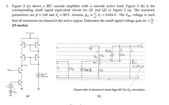
2. Figure 2 (a) shows a BJT cascode amplifier with a cascode active load. Figure 2 (b) is the corresponding small signal
Posted: Sun May 15, 2022 8:40 pm
by answerhappygod
- 2 Figure 2 A Shows A Bjt Cascode Amplifier With A Cascode Active Load Figure 2 B Is The Corresponding Small Signal 1 (34.25 KiB) Viewed 44 times
2. Figure 2 (a) shows a BJT cascode amplifier with a cascode active load. Figure 2 (b) is the corresponding small signal equivalent circuit for Q1 and Q2 in Figure 2 (a). The transistor parameters are ß = 120 and Vi = 80 V. Assume 9m >>V, = 0.026 V. The Vpe voltage is such that all transistors are biased in the active region. Determine the small signal voltage gain Av (15 marks) VSV es V T انجمن را F 1 4 0 mia 3 rol 250 g Please refer to Neamen's book Page 697 for Roz derivation (b) (a)