Page 1 of 1
Section 7. The Asynchronous Counter (a) Connect the circuit for the asynchronous counter as shown in Fig. 6. It consists
Posted: Sun May 15, 2022 8:36 pm
by answerhappygod
- Section 7 The Asynchronous Counter A Connect The Circuit For The Asynchronous Counter As Shown In Fig 6 It Consists 1 (48.98 KiB) Viewed 49 times
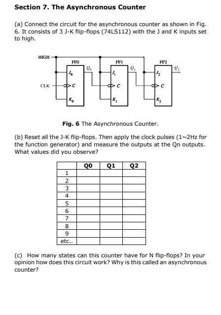
Section 7. The Asynchronous Counter (a) Connect the circuit for the asynchronous counter as shown in Fig. 6. It consists of 3 J-K flip-flops (74LS112) with the ) and K inputs set to high. HIGH FFO FFI FF2 e " 4 12 CLK ФС PC ФС K K K2 Fig. 6 The Asynchronous Counter. (b) Reset all the 3-K flip-flops. Then apply the clock pulses (1~2Hz for the function generator) and measure the outputs at the Qn outputs. What values did you observe? QO Q1 Q2 1 2 3 4 5 6 7 8 9 etc.. (C) How many states can this counter have for N flip-flops? In your opinion how does this circuit work? Why is this called an asynchronous counter?