Page 1 of 1
Section 4. Implementation of a Half Adder (a) Construct the circuit as shown in Fig. 3. Vary the inputs A and B (i.e. 0
Posted: Sun May 15, 2022 8:34 pm
by answerhappygod
- Section 4 Implementation Of A Half Adder A Construct The Circuit As Shown In Fig 3 Vary The Inputs A And B I E 0 1 (69.36 KiB) Viewed 29 times
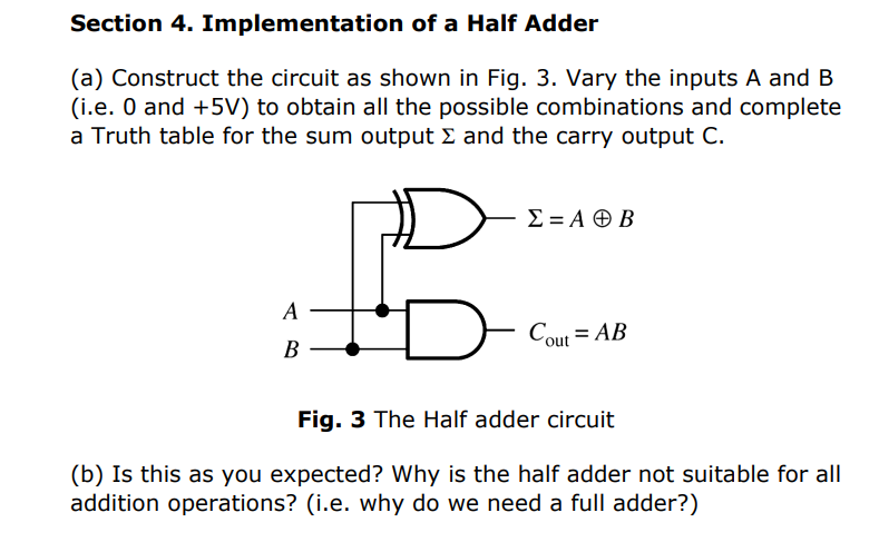
Section 4. Implementation of a Half Adder (a) Construct the circuit as shown in Fig. 3. Vary the inputs A and B (i.e. 0 and +5V) to obtain all the possible combinations and complete a Truth table for the sum output & and the carry output C. Σ = ΑΦ B А Cout = AB B Fig. 3 The Half adder circuit (b) Is this as you expected? Why is the half adder not suitable for all addition operations? (i.e. why do we need a full adder?)