Page 1 of 1
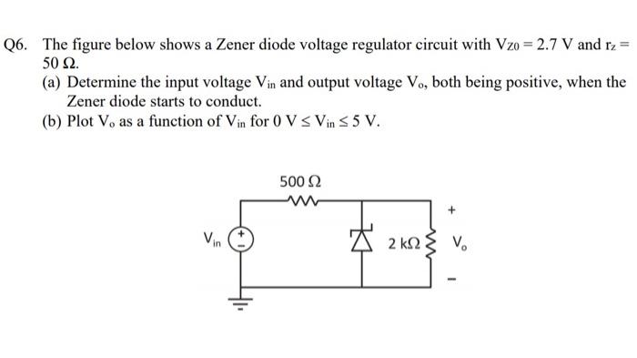
Q6. The figure below shows a Zener diode voltage regulator circuit with Vzo = 2.7 V and rz = 50 Ω. (a) Determine the inp
Posted: Sun May 15, 2022 8:32 pm
by answerhappygod
- 1 (22.54 KiB) Viewed 29 times
Q6. The figure below shows a Zener diode voltage regulator circuit with Vzo = 2.7 V and rz = 50 Ω. (a) Determine the input voltage Vin and output voltage V., both being positive, when the Zener diode starts to conduct. (b) Plot V, as a function of Vin for 0 V s Vins 5 V. 500 Ω Vin Δ 2 ΚΩξ να k2