Page 1 of 1
6. Fig. 5 shows an IPT circuit. Derive an equation giving the impedance of the secondary (Zs), separated into its real a
Posted: Sun May 15, 2022 8:13 pm
by answerhappygod
- 6 Fig 5 Shows An Ipt Circuit Derive An Equation Giving The Impedance Of The Secondary Zs Separated Into Its Real A 1 (118.4 KiB) Viewed 42 times
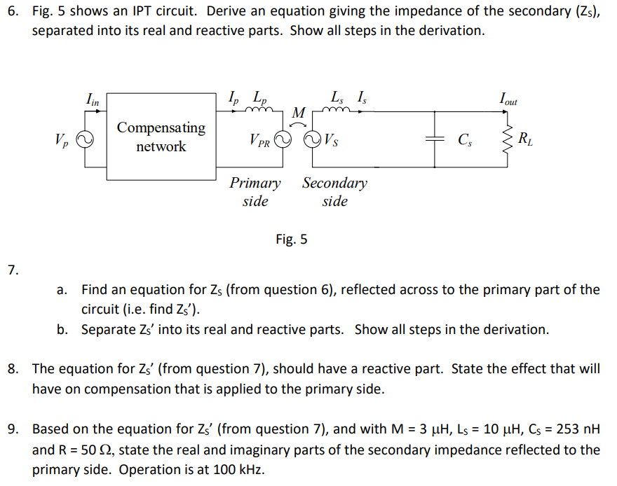
6. Fig. 5 shows an IPT circuit. Derive an equation giving the impedance of the secondary (Zs), separated into its real and reactive parts. Show all steps in the derivation. lin I, Lp Ls 15 Tout M Ve Compensating network V PR VS Cs RL w Primary side Secondary side Fig. 5 7. a. Find an equation for Zs (from question 6), reflected across to the primary part of the circuit (i.e. find Zs'). b. Separate Zs' into its real and reactive parts. Show all steps in the derivation. 8. The equation for Zs' (from question 7), should have a reactive part. State the effect that will have on compensation that is applied to the primary side. = 9. Based on the equation for Zs' (from question 7), and with M = 3 uH, Ls = 10 uH, Cs = 253 nH and R = 50 92, state the real and imaginary parts of the secondary impedance reflected to the primary side. Operation is at 100 kHz.