Page 1 of 1
5. For the circuit shown in Fig. 4 it is desired to find the Thevenin equivalent circuit, with the output terminals take
Posted: Sun May 15, 2022 8:13 pm
by answerhappygod
- 5 For The Circuit Shown In Fig 4 It Is Desired To Find The Thevenin Equivalent Circuit With The Output Terminals Take 1 (93.15 KiB) Viewed 70 times
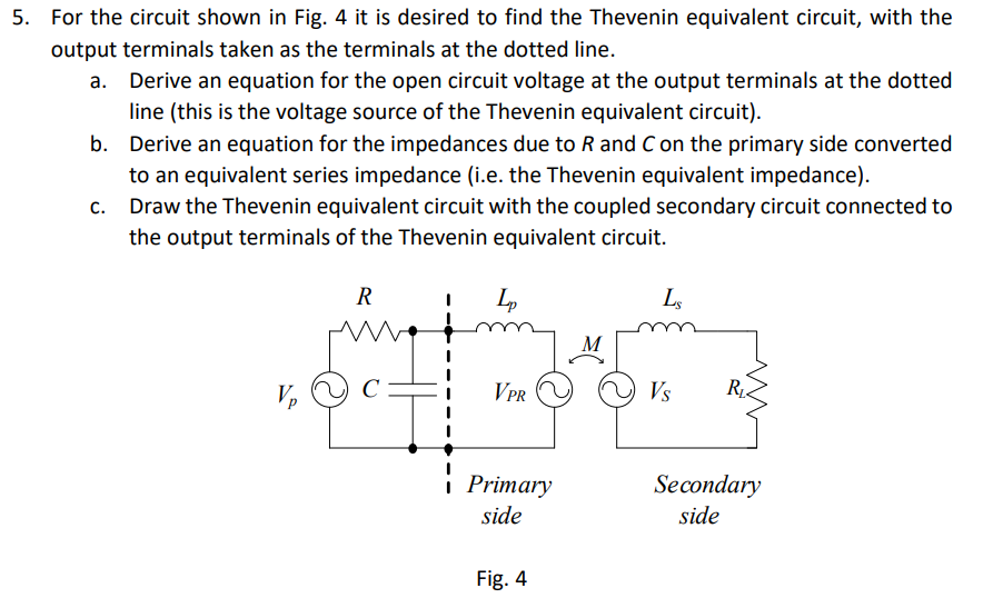
5. For the circuit shown in Fig. 4 it is desired to find the Thevenin equivalent circuit, with the output terminals taken as the terminals at the dotted line. a. Derive an equation for the open circuit voltage at the output terminals at the dotted line (this is the voltage source of the Thevenin equivalent circuit). b. Derive an equation for the impedances due to R and C on the primary side converted to an equivalent series impedance (i.e. the Thevenin equivalent impedance). C. Draw the Thevenin equivalent circuit with the coupled secondary circuit connected to the output terminals of the Thevenin equivalent circuit. R Lp LS be M M V С V PR Vs R i Primary i side Secondary side Fig. 4