Page 1 of 1
4. Fig. 3 shows a capacitive power transfer circuit. For this circuit inductor Lp forms a resonant circuit with C1, C2 a
Posted: Sun May 15, 2022 8:12 pm
by answerhappygod
- 4 Fig 3 Shows A Capacitive Power Transfer Circuit For This Circuit Inductor Lp Forms A Resonant Circuit With C1 C2 A 1 (62.43 KiB) Viewed 29 times
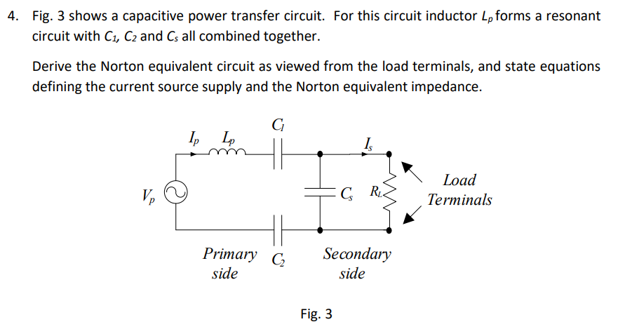
4. Fig. 3 shows a capacitive power transfer circuit. For this circuit inductor Lp forms a resonant circuit with C1, C2 and Cs all combined together. Derive the Norton equivalent circuit as viewed from the load terminals, and state equations defining the current source supply and the Norton equivalent impedance. G Ip L IS Ve GRE Load Terminals Primary CZ Secondary side side Fig. 3