Page 1 of 1
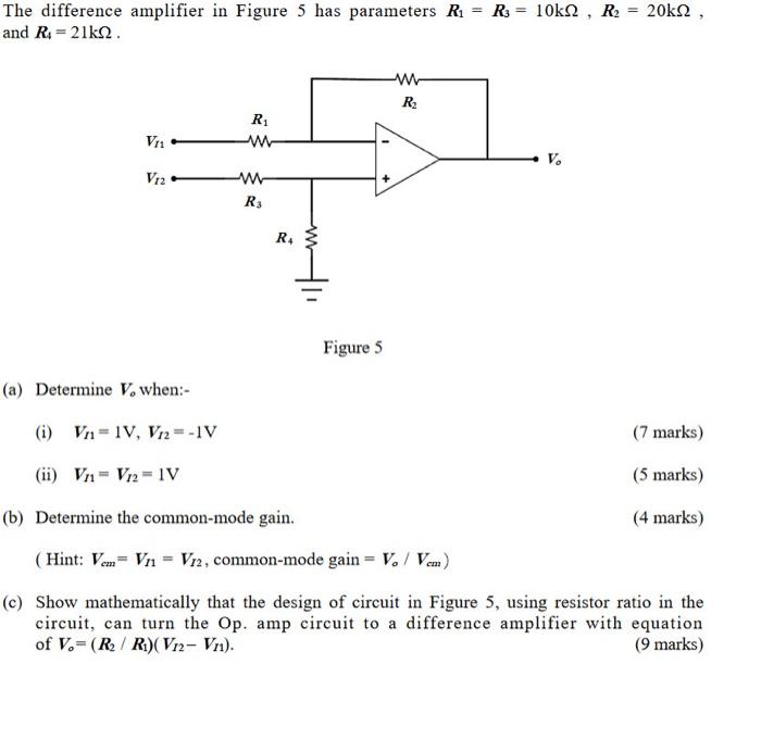
The difference amplifier in Figure 5 has parameters R1 = Rs = 10kN , R2 = 20kN , and R.218.2. w R R VI V. V12 w R: R. Fi
Posted: Sun May 15, 2022 8:02 pm
by answerhappygod
- The Difference Amplifier In Figure 5 Has Parameters R1 Rs 10kn R2 20kn And R 218 2 W R R Vi V V12 W R R Fi 1 (36.25 KiB) Viewed 30 times
The difference amplifier in Figure 5 has parameters R1 = Rs = 10kN , R2 = 20kN , and R.218.2. w R R VI V. V12 w R: R. Figure 5 (a) Determine V, when:- (i) Vn=1V, V12=-IV (7 marks) (ii) Vn - Vr2 1V (5 marks) (b) Determine the common-mode gain. (4 marks) (Hint: Vcm= Vn = V12, common-mode gain = V. / Vem) (c) Show mathematically that the design of circuit in Figure 5, using resistor ratio in the circuit, can turn the Op. amp circuit to a difference amplifier with equation of V.- ( RR) (V12- Vn). (9 marks)