Page 1 of 1
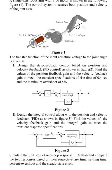
figure (1). The control system measures both position and velocity of the joint axis. Robotie Arm Gearing 2.-10 x 10"k 1
Posted: Sun May 15, 2022 7:53 pm
by answerhappygod
- Figure 1 The Control System Measures Both Position And Velocity Of The Joint Axis Robotie Arm Gearing 2 10 X 10 K 1 1 (52.38 KiB) Viewed 42 times
figure (1). The control system measures both position and velocity of the joint axis. Robotie Arm Gearing 2.-10 x 10"k 1-16x 10kg Joint Axis IX Motor Figure 1 The transfer function of the input armature voltage to the joint angle is given as I. Design the state-feedback control based on position and velocity feedback (PD control) as shown in figure(2). Find the values of the position feedback gain and the velocity feedback gain to meet the transient specifications of rise time of 0.4 sec and the maximum overshoot of 5%. s(0,*+0) Figure 2 II. Design the integral control along with the position and velocity feedback (PID) as shown in figure(3). Find the values of the velocity feedback gain and the integral gain to meet the transient response specifications. ${4,8+) Figure 3 Simulate the unit step closed-loop response in Matlab and compare the two responses based on their respective rise time, settling time, percent-overshoot and the steady-state error.