Page 1 of 1
1.2. Inverter propagation delays a [R1.2.1] (0.4 mark) Use six NOT gates (74LS04) in sequence, with a clock (square wave
Posted: Sun May 15, 2022 7:30 pm
by answerhappygod
- 1 2 Inverter Propagation Delays A R1 2 1 0 4 Mark Use Six Not Gates 74ls04 In Sequence With A Clock Square Wave 1 (237.92 KiB) Viewed 31 times
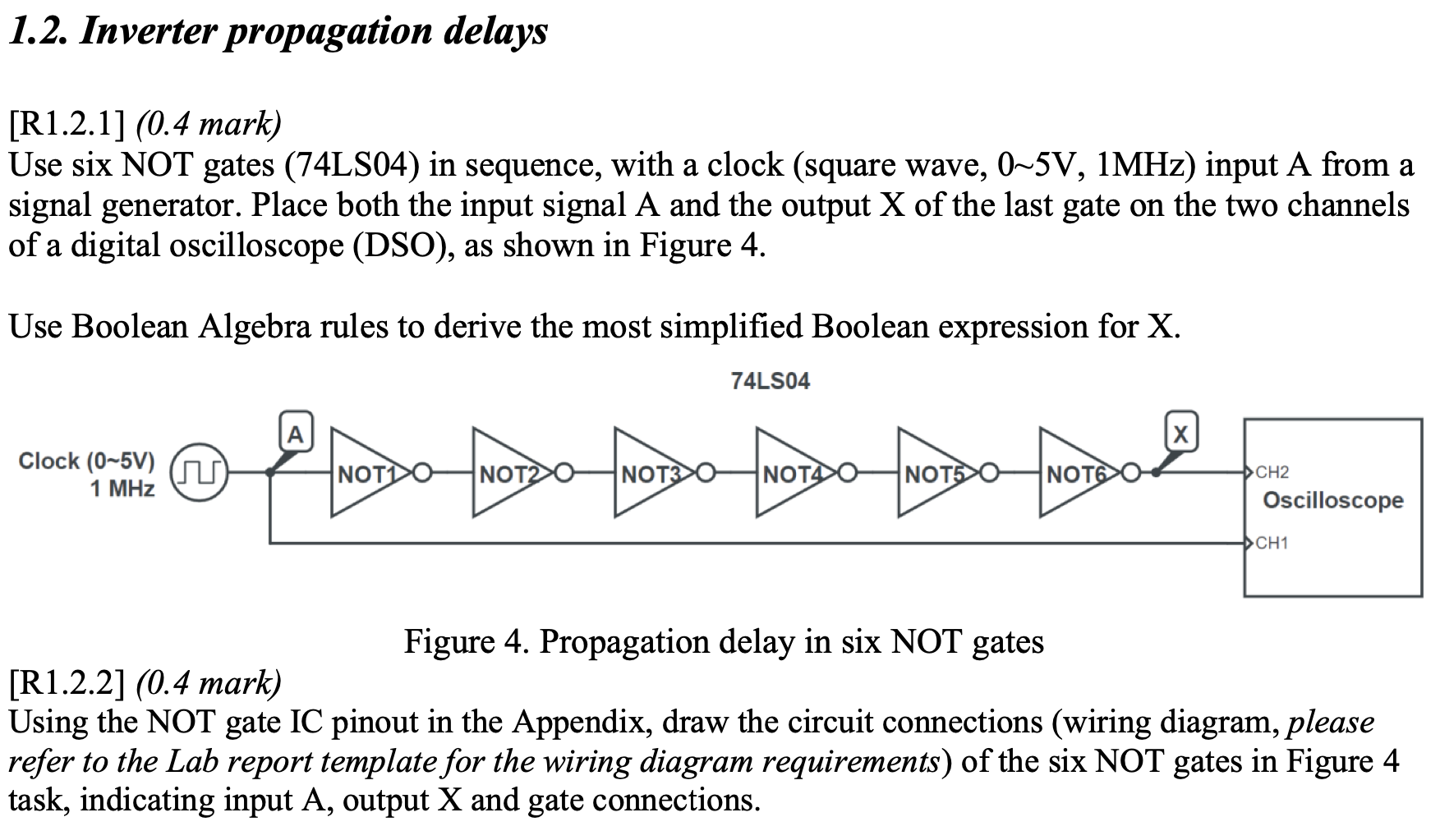
1.2. Inverter propagation delays a [R1.2.1] (0.4 mark) Use six NOT gates (74LS04) in sequence, with a clock (square wave, 0-5V, 1MHz) input A from a signal generator. Place both the input signal A and the output X of the last gate on the two channels of a digital oscilloscope (DSO), as shown in Figure 4. Use Boolean Algebra rules to derive the most simplified Boolean expression for X. A х C-- Clock (0-5V) G NOTDO NOTO NOT30 NOT50 NOT6 CH2 1 MHz © རྩིས་གང་བ་བྱུང་བས་མ་མྱོང་ལ་མ་ཐུགས་མ་ཐུབ་པ་བྱེད་ཀྱི --- Oscilloscope CH1 Figure 4. Propagation delay in six NOT gates [R1.2.2] (0.4 mark) Using the NOT gate IC pinout in the Appendix, draw the circuit connections (wiring diagram, please refer to the Lab report template for the wiring diagram requirements) of the six NOT gates in Figure 4 task, indicating input A, output X and gate connections.