Page 1 of 1
2. Follow the procedure followed in part 1 to solve problem B-6-17 in your text reproduced below B-6-17. Consider the sy
Posted: Sun May 15, 2022 7:29 pm
by answerhappygod
- 2 Follow The Procedure Followed In Part 1 To Solve Problem B 6 17 In Your Text Reproduced Below B 6 17 Consider The Sy 1 (29.59 KiB) Viewed 54 times
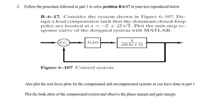
2. Follow the procedure followed in part 1 to solve problem B-6-17 in your text reproduced below B-6-17. Consider the system shown in Figure 6-107. De- sign a lead compensator such that the dominant closed-loop poles are located at s = -2 + 2V3. Plot the unit-step re- sponse curve of the designed system with MATLAB. G.) 5 $(0.5x + 1) Figure 6-107 Control system. Also plot the root locus plots for the compensated and uncompensated systems as you have done in part 1 Plot the bode plots of the compensated system and observe the phase margin and gain margin.