Page 1 of 1
1.1. Basic logic gates Choose any TWO of the basic logic gates from OR(74LS32), AND(74LS08), NAND(74LS00) and NOR(74LS02
Posted: Sun May 15, 2022 7:28 pm
by answerhappygod
- 1 1 Basic Logic Gates Choose Any Two Of The Basic Logic Gates From Or 74ls32 And 74ls08 Nand 74ls00 And Nor 74ls02 1 (161.49 KiB) Viewed 39 times
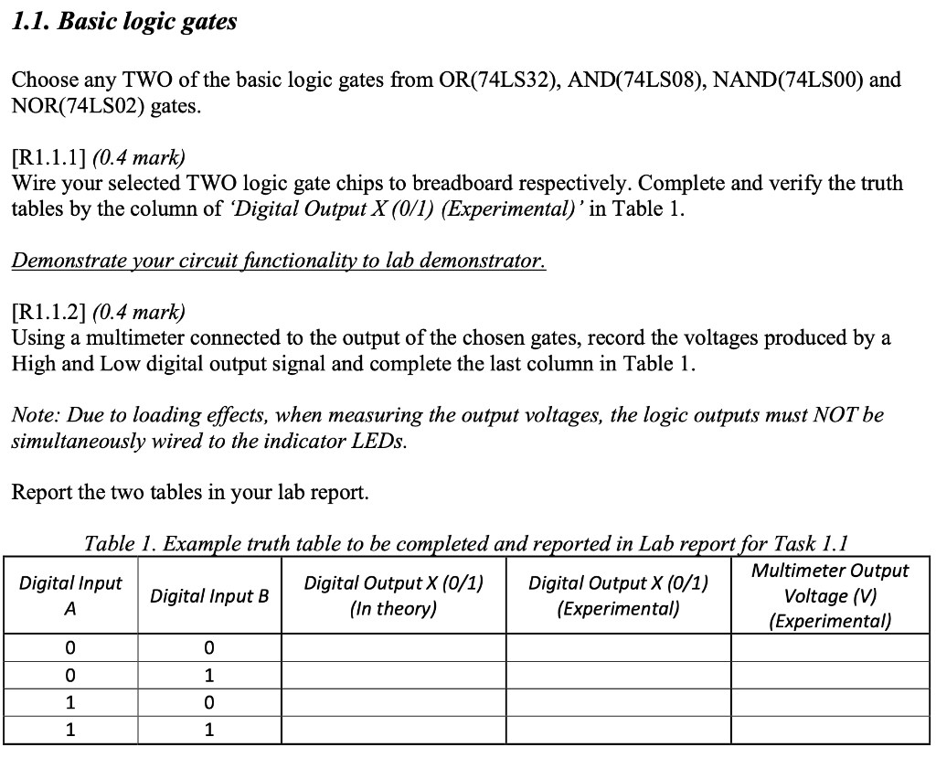
1.1. Basic logic gates Choose any TWO of the basic logic gates from OR(74LS32), AND(74LS08), NAND(74LS00) and NOR(74LS02) gates. [R1.1.1] (0.4 mark) Wire your selected TWO logic gate chips to breadboard respectively. Complete and verify the truth tables by the column of 'Digital Output X (0/1) (Experimental)'in Table 1. Demonstrate your circuit functionality to lab demonstrator. [R1.1.2] (0.4 mark) Using a multimeter connected to the output of the chosen gates, record the voltages produced by a High and Low digital output signal and complete the last column in Table 1. Note: Due to loading effects, when measuring the output voltages, the logic outputs must NOT be simultaneously wired to the indicator LEDs. Report the two tables in your lab report. Table 1. Example truth table to be completed and reported in Lab report for Task 1.1 Multimeter Output Digital Input Digital Output X (0/1) Digital Output X (0/1) Digital Input B Voltage (V) A (In theory) (Experimental) (Experimental) 0 0 0 1 1 0 1 1