Page 1 of 1
VCC a. For the circuit as shown in Fig.2 determine the Q-points [Q(Vce, l)] due to changes in ß between 50 and 200. cons
Posted: Sun May 15, 2022 6:31 pm
by answerhappygod
- Vcc A For The Circuit As Shown In Fig 2 Determine The Q Points Q Vce L Due To Changes In Ss Between 50 And 200 Cons 1 (102.07 KiB) Viewed 59 times
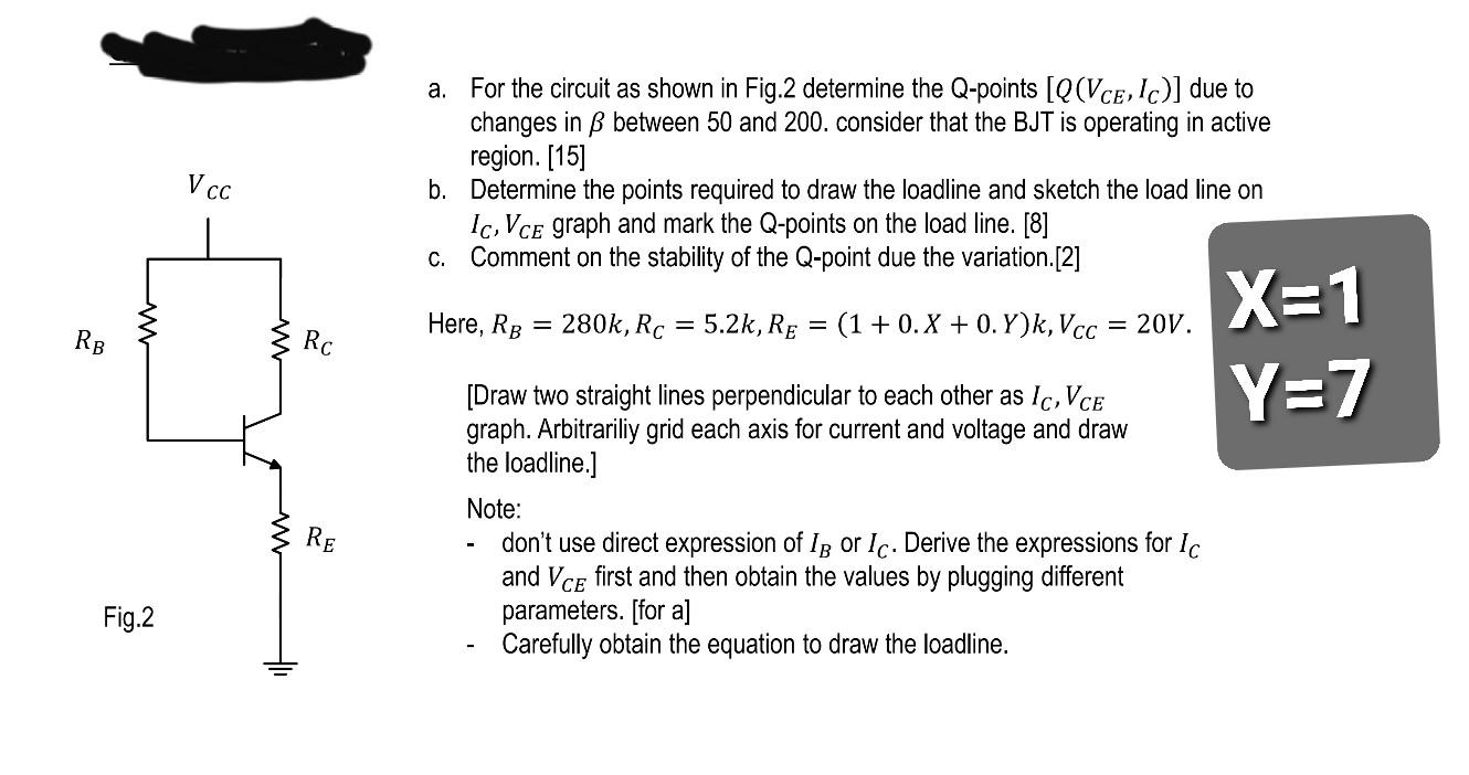
VCC a. For the circuit as shown in Fig.2 determine the Q-points [Q(Vce, l)] due to changes in ß between 50 and 200. consider that the BJT is operating in active region. [15] b. Determine the points required to draw the loadline and sketch the load line on Ic, Vce graph and mark the Q-points on the load line. [8] C. Comment on the stability of the Q-point due the variation.[2] Here, RB = 280k, Rc = 5.2k, Re = (1 + 0.X + 0.Y)k, Vcc = 20V. = = RB Rc X=1 Y=7 [Draw two straight lines perpendicular to each other as Ic, VCE graph. Arbitrariliy grid each axis for current and voltage and draw the loadline.] Note: don't use direct expression of Ip or Ic. Derive the expressions for Ic and Vce first and then obtain the values by plugging different parameters. [for a] Carefully obtain the equation to draw the loadline. RE Fig.2