Page 1 of 1
2.1 Firstly, calculate the time constant of the circuit. Then, build the circuit given in Figure-4 below. Initially disc
Posted: Sun May 15, 2022 6:29 pm
by answerhappygod
- 2 1 Firstly Calculate The Time Constant Of The Circuit Then Build The Circuit Given In Figure 4 Below Initially Disc 1 (273.93 KiB) Viewed 69 times
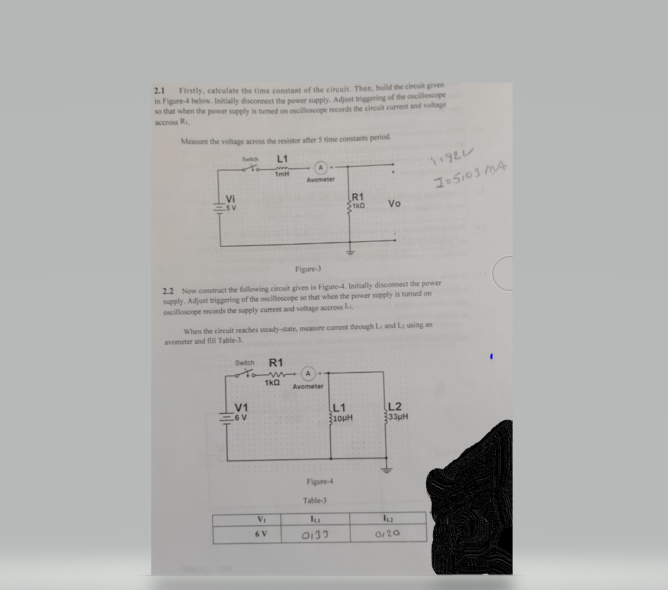
2.1 Firstly, calculate the time constant of the circuit. Then, build the circuit given in Figure-4 below. Initially disconnect the power supply, Adjust triggering of the oscilloscope so that when the power supply is turned on oscilloscope records the circuit current and voltage accross R Measure the voltage across the resistor after 5 time constants period. Switch L1 سا192 1mH Avometer I=5103 MA Vi - 5 V R1 S1ko Vo Figure-3 2.2 Now construct the following circuit given in Figure-4. Initially disconnect the power supply. Adjust triggering of the oscilloscope so that when the power supply is turned on oscilloscope records the supply current and voltage accross L. When the circuit reaches steady-state, measure current through Land La using an avometer and fill Table-3. Switch R1 A 1kg Avometer V1 6V L1 310ин L2 333H Figure-4 Table-3 Vi lu 6V 0133 0120
3.4 Write an expression for the current and resistor voltage V.for the circuit in Figure-3. Plot the variation of current and voltage of V.. Compare your plots with the recording from the oscilloscope (magnitude and time variation). Comment on the results. 3.5 Write an expression for the current through R, and voltage across the inductors for the circuit in Figure-4. Plot the variation of power supply current and inductor voltage. Compare your plots with the recording from the oscilloscope (magnitude and time variation). Comment on the results.