Page 1 of 1
Task 3 Construct the following circuit in Figure P4.3 to simulate: XSC1 100k RE w 10ka V1 R1 0.5 Vpk 1kHz 09 OPAMP 3T VI
Posted: Sun May 15, 2022 6:15 pm
by answerhappygod
- Task 3 Construct The Following Circuit In Figure P4 3 To Simulate Xsc1 100k Re W 10ka V1 R1 0 5 Vpk 1khz 09 Opamp 3t Vi 1 (31.31 KiB) Viewed 56 times
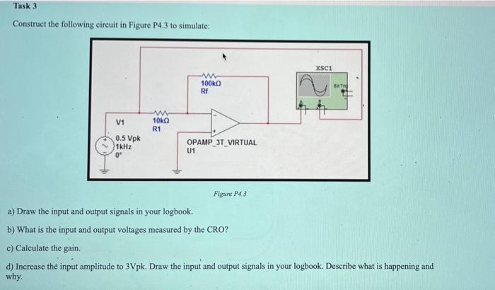
Task 3 Construct the following circuit in Figure P4.3 to simulate: XSC1 100k RE w 10ka V1 R1 0.5 Vpk 1kHz 09 OPAMP 3T VIRTUAL U1 Figure P43 a) Draw the input and output signals in your logbook. b) What is the input and output voltages measured by the CRO? c) Calculate the gain. d) Increase the input amplitude to 3Vpk. Draw the input and output signals in your logbook. Describe what is happening and why.