Page 1 of 1
The block diagram of C/D and D/C system is shown below. p(t) DT LTI System CT lowpass Filter xc(t) Xp (6) Conversion of
Posted: Sun May 15, 2022 5:54 pm
by answerhappygod
- The Block Diagram Of C D And D C System Is Shown Below P T Dt Lti System Ct Lowpass Filter Xc T Xp 6 Conversion Of 1 (124.07 KiB) Viewed 55 times
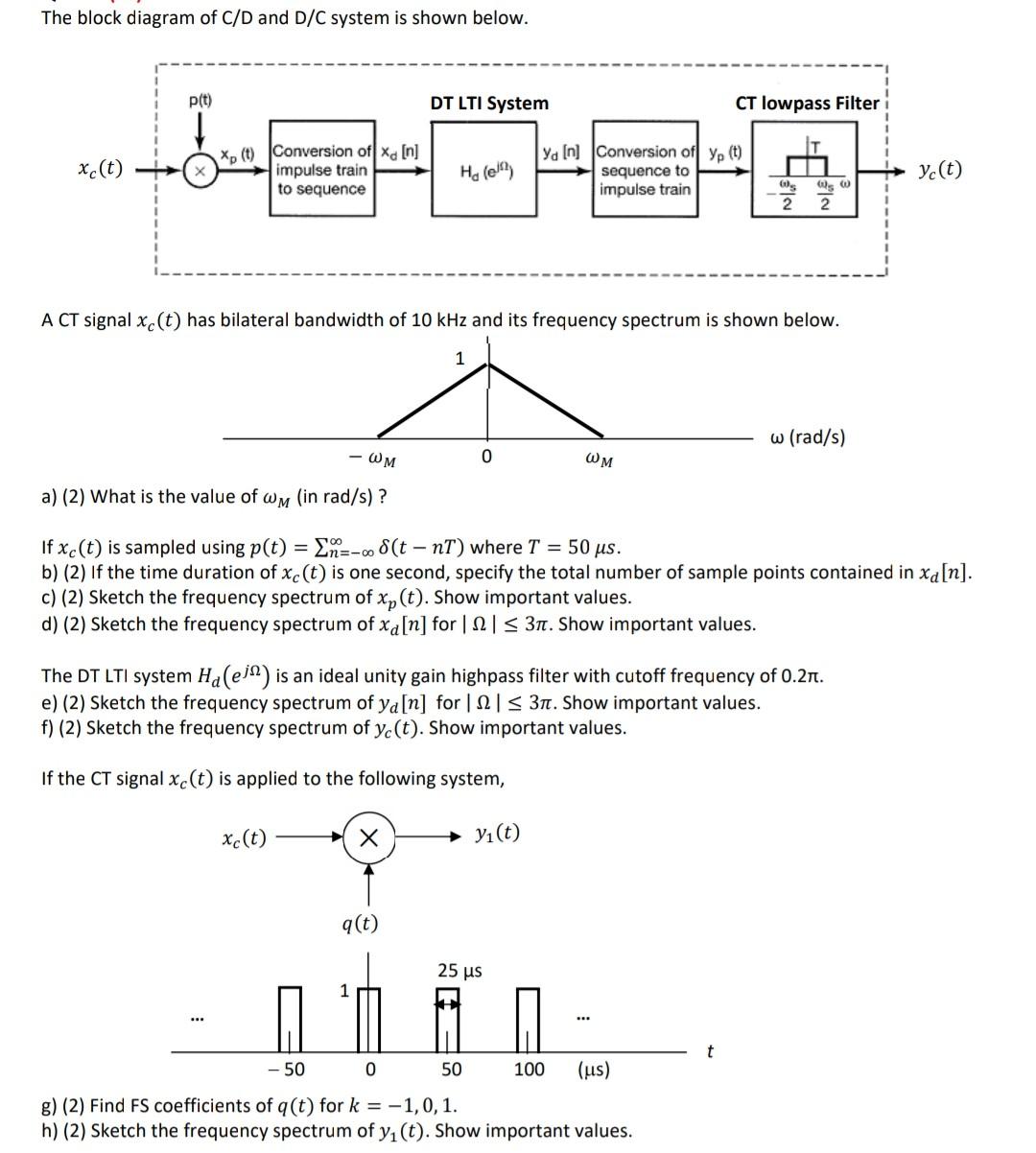
The block diagram of C/D and D/C system is shown below. p(t) DT LTI System CT lowpass Filter xc(t) Xp (6) Conversion of xa [n] impulse train to sequence He fell ya In Conversion of yp (t) sequence to impulse train y(t) Os 60 2 2 A CT signal xc(t) has bilateral bandwidth of 10 kHz and its frequency spectrum is shown below. 1 w (rad/s) -WM 0 OM a) (2) What is the value of wm (in rad/s)? n-00 - If xc(t) is sampled using p(t) EN--8(t - nT) where T = 50 us. b) (2) If the time duration of xc(t) is one second, specify the total number of sample points contained in xa[n]. c) (2) Sketch the frequency spectrum of xp (t). Show important values. d) (2) Sketch the frequency spectrum of xa[n] for 12 = 31. Show important values. The DT LTI system Ha(ejn) is an ideal unity gain highpass filter with cutoff frequency of 0.27. e) (2) Sketch the frequency spectrum of ya[n] for 12 = 31. Show important values. f) (2) Sketch the frequency spectrum of y(t). Show important values. If the CT signal xc(t) is applied to the following system, xc(t) X yı(t) q(t) 25 us ... - 50 0 50 100 (us) g) (2) Find FS coefficients of q(t) for k = -1,0,1. h) (2) Sketch the frequency spectrum of yı(t). Show important values.