Page 1 of 1
1 Interpreting Bode Plots Shown below are the closed-loop Bode magnitude plots for 4 transfer functions G1, G2, G3, and
Posted: Sun May 15, 2022 5:39 pm
by answerhappygod
- 1 Interpreting Bode Plots Shown Below Are The Closed Loop Bode Magnitude Plots For 4 Transfer Functions G1 G2 G3 And 1 (176.31 KiB) Viewed 47 times
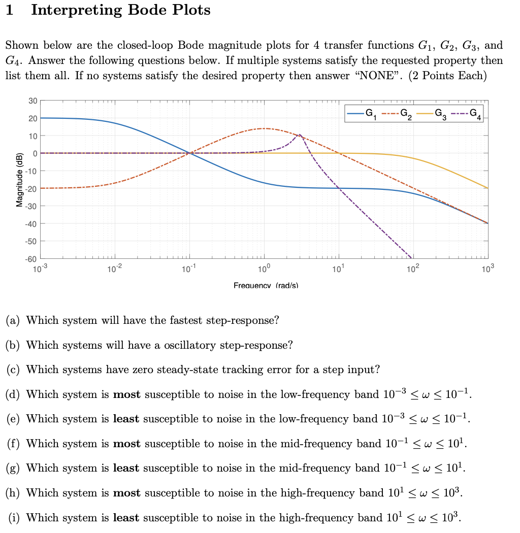
1 Interpreting Bode Plots Shown below are the closed-loop Bode magnitude plots for 4 transfer functions G1, G2, G3, and G4. Answer the following questions below. If multiple systems satisfy the requested property then list them all. If no systems satisfy the desired property then answer "NONE”. (2 Points Each) 30 G 1 -G2 G 20 10 0 Magnitude (dB) -20 -30 -40 -50 -60 103 10-2 10-1 100 101 102 103 Frequency (rad/s) a) Which system will have the fastest step-response? (b) Which systems will have a oscillatory step-response? Which systems have zero steady-state tracking error for a step input? (d) Which system is most susceptible to noise in the low-frequency band 10-3 SW S 10-1. (e) Which system is least susceptible to noise in the low-frequency band 10-3 SW S 10-1. (f) Which system is most susceptible to noise in the mid-frequency band 10-1 SW < 101. (g) Which system is least susceptible to noise in the mid-frequency band 10-1 5w < 101. (h) Which system is most susceptible to noise in the high-frequency band 101 <w < 103. (i) Which system is least susceptible to noise in the high-frequency band 101 <w < 10%.