Page 1 of 1
1. For the circuit in Figure 1, using the datasheet or the parameters extracted in the previous lab, calculate the resis
Posted: Sun May 15, 2022 5:27 pm
by answerhappygod
- 1 For The Circuit In Figure 1 Using The Datasheet Or The Parameters Extracted In The Previous Lab Calculate The Resis 1 (88.28 KiB) Viewed 39 times
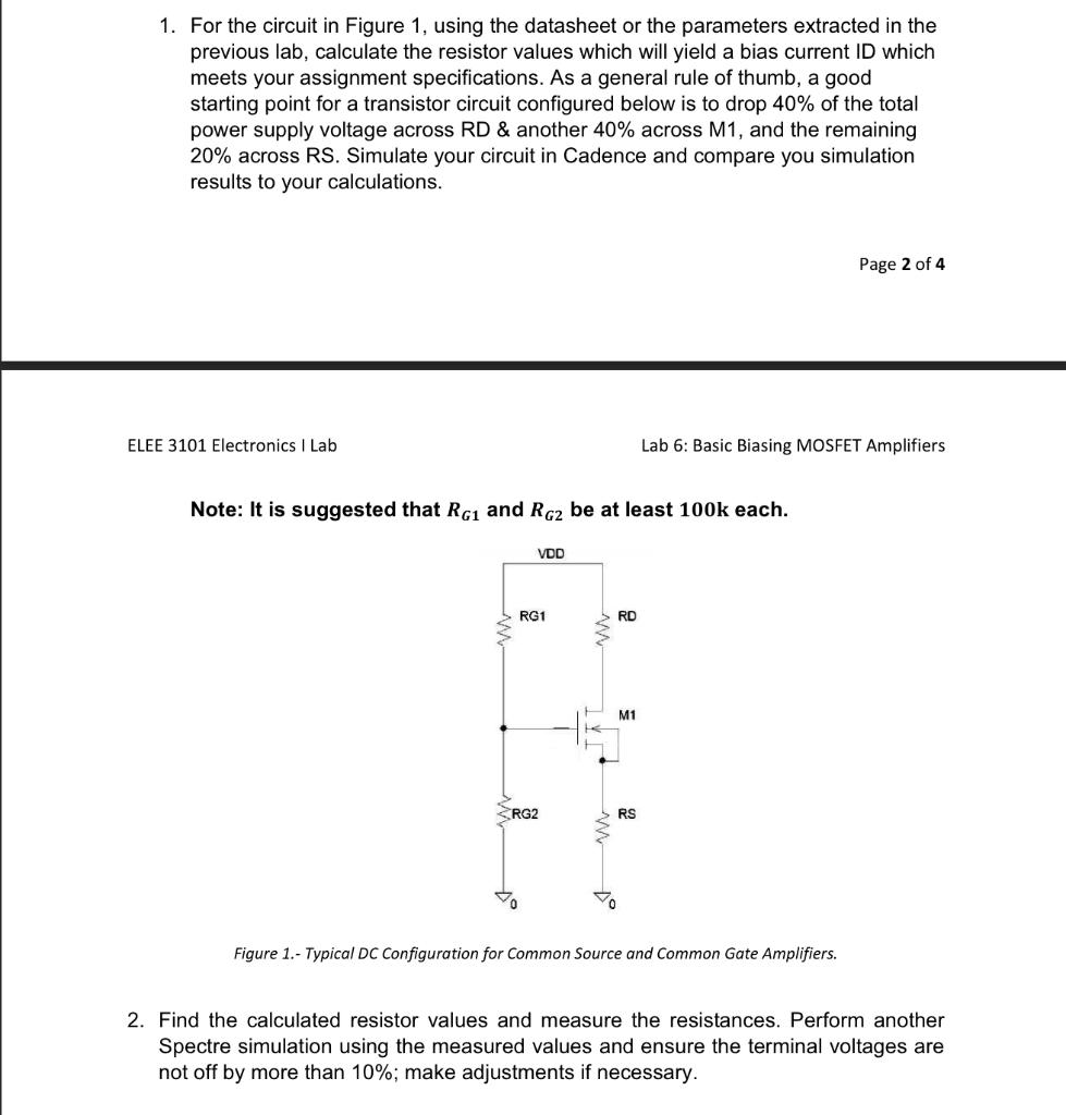
1. For the circuit in Figure 1, using the datasheet or the parameters extracted in the previous lab, calculate the resistor values which will yield a bias current ID which meets your assignment specifications. As a general rule of thumb, a good starting point for a transistor circuit configured below is to drop 40% of the total power supply voltage across RD & another 40% across M1, and the remaining 20% across RS. Simulate your circuit in Cadence and compare you simulation results to your calculations. Page 2 of 4 ELEE 3101 Electronics I Lab Lab 6: Basic Biasing MOSFET Amplifiers Note: It is suggested that RG1 and RG2 be at least 100k each. VOD RG1 RD M1 RG2 RS W Figure 1.- Typical DC Configuration for Common Source and Common Gate Amplifiers. 2. Find the calculated resistor values and measure the resistances. Perform another Spectre simulation using the measured values and ensure the terminal voltages are not off by more than 10%; make adjustments if necessary.