Page 1 of 1
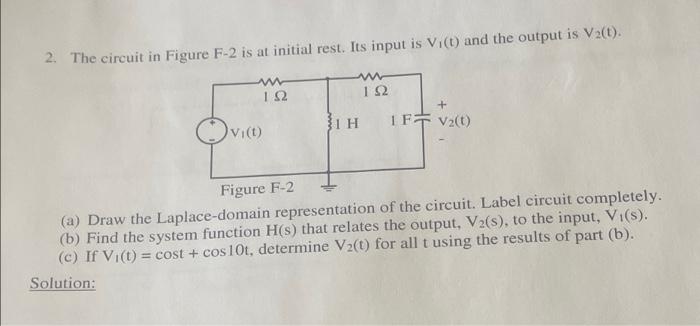
2. The circuit in Figure F-2 is at initial rest. Its input is V. (t) and the output is V2(t). W 192 192 IFVzt) vict) BIH
Posted: Sun May 15, 2022 5:19 pm
by answerhappygod
- 2 The Circuit In Figure F 2 Is At Initial Rest Its Input Is V T And The Output Is V2 T W 192 192 Ifvzt Vict Bih 1 (22.93 KiB) Viewed 46 times
2. The circuit in Figure F-2 is at initial rest. Its input is V. (t) and the output is V2(t). W 192 192 IFVzt) vict) BIH Figure F-2 (a) Draw the Laplace-domain representation of the circuit. Label circuit completely. (b) Find the system function H(s) that relates the output, V2(s), to the input, V.(s). (c) If Vi(t) = cost + cos 10t, determine V2(1) for all t using the results of part (b). Solution: