Page 1 of 1
The block diagram of C/D and D/C system is shown below. p(t) DT LTI System CT lowpass Filter xc(t) Xp (t) Conversion of
Posted: Sun May 15, 2022 4:52 pm
by answerhappygod
- The Block Diagram Of C D And D C System Is Shown Below P T Dt Lti System Ct Lowpass Filter Xc T Xp T Conversion Of 1 (114.63 KiB) Viewed 56 times
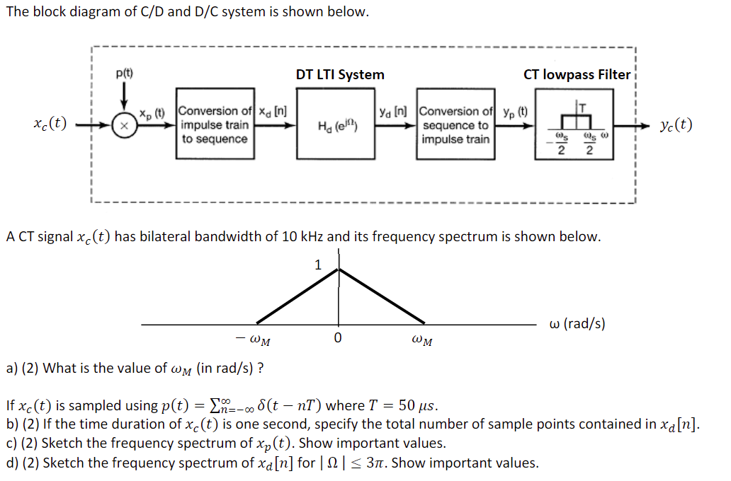
The block diagram of C/D and D/C system is shown below. p(t) DT LTI System CT lowpass Filter xc(t) Xp (t) Conversion of xa [n] x impulse train to sequence Ha (el ya In Conversion of yp (t) sequence to impulse train yo(t) neh 2 2 A CT signal xc(t) has bilateral bandwidth of 10 kHz and its frequency spectrum is shown below. 1 w (rad/s) OM ωM a) (2) What is the value of wm (in rad/s)? - If xc(t) is sampled using p(t) = {n--8(t - nT) where T = 50 us. b) (2) If the time duration of xc(t) is one second, specify the total number of sample points contained in xa[n]. c) (2) Sketch the frequency spectrum of xp(t). Show important values. d) (2) Sketch the frequency spectrum of xa[n] for | 12 | 531. Show important values.