Page 1 of 1
For the common emitter circuit shown in Figure 3, let B = 80, VBe(on) = 0.7 V, Vcc= 12 V, ICQ = 0.8 mA, VceQ = 4 V, and
Posted: Sun May 15, 2022 4:51 pm
by answerhappygod
- For The Common Emitter Circuit Shown In Figure 3 Let B 80 Vbe On 0 7 V Vcc 12 V Icq 0 8 Ma Vceq 4 V And 1 (28.76 KiB) Viewed 62 times
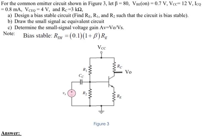
For the common emitter circuit shown in Figure 3, let B = 80, VBe(on) = 0.7 V, Vcc= 12 V, ICQ = 0.8 mA, VceQ = 4 V, and Rc =3 k12, a) Design a bias stable circuit (Find Re, R1, and R2 such that the circuit is bias stable). b) Draw the small signal ac equivalent circuit c) Determine the small-signal voltage gain Av=Vo/Vs. Bias stable: Ryu = (0.1)(1+B)Rg Vec Rc R1 Cc www Vo HE R2 ww Figure 3 Answer: