Page 1 of 1
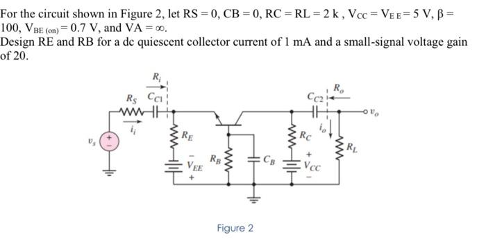
For the circuit shown in Figure 2, let RS = 0, CB = 0, RC = RL = 2 k , Vcc = Vee=5 V, B = 100, VBE (on)=0.7 V, and VA =
Posted: Sun May 15, 2022 4:51 pm
by answerhappygod
- For The Circuit Shown In Figure 2 Let Rs 0 Cb 0 Rc Rl 2 K Vcc Vee 5 V B 100 Vbe On 0 7 V And Va 1 (23.13 KiB) Viewed 42 times
For the circuit shown in Figure 2, let RS = 0, CB = 0, RC = RL = 2 k , Vcc = Vee=5 V, B = 100, VBE (on)=0.7 V, and VA = 0. Design RE and RB for a de quiescent collector current of 1 mA and a small-signal voltage gain of 20. R R. Rs Cal RE RC will www RL VEE RB HE Св V cc w Figure 2