Page 1 of 1
4. A Buck converter has the following parameters and is operating in CCM: L = 100 uH; C = 700uF; r = 0.112; fs = 100 kHz
Posted: Sun May 15, 2022 4:49 pm
by answerhappygod
- 4 A Buck Converter Has The Following Parameters And Is Operating In Ccm L 100 Uh C 700uf R 0 112 Fs 100 Khz 1 (80.7 KiB) Viewed 48 times
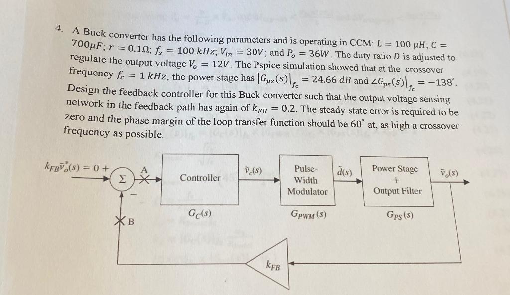
4. A Buck converter has the following parameters and is operating in CCM: L = 100 uH; C = 700uF; r = 0.112; fs = 100 kHz; Vin = 30V; and P. = 36W. The duty ratio D is adjusted to regulate the output voltage V6 = 12V. The Pspice simulation showed that at the crossover frequency fo = 1 kHz, the power stage has | Gps()lf. = 24.66 dB and ZGps (s) se = -138". Design the feedback controller for this Buck converter such that the output voltage sensing network in the feedback path has again of kpl = 0.2. The steady state error is required to be zero and the phase margin of the loop transfer function should be 60° at, as high a crossover frequency as possible. kFBŪ(s) = 0 + A (s) d's) Σ Controller 7.) Pulse- Width Modulator Power Stage + Output Filter Gc(s) GPWM (5) XB Gps (5) KFB