Page 1 of 1
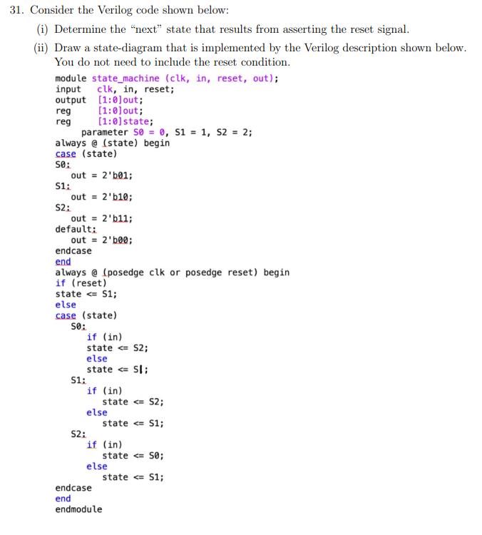
31. Consider the Verilog code shown below: (i) Determine the “next” state that results from asserting the reset signal.
Posted: Sun May 15, 2022 4:37 pm
by answerhappygod
- 31 Consider The Verilog Code Shown Below I Determine The Next State That Results From Asserting The Reset Signal 1 (122.64 KiB) Viewed 87 times
31. Consider the Verilog code shown below: (i) Determine the “next” state that results from asserting the reset signal. (ii) Draw a state-diagram that is implemented by the Verilog description shown below. You do not need to include the reset condition. module state_machine (clk, in, reset, out); input clk, in, reset; output (1:0) out; reg (1:0) out; (1:0) state; parameter so = 0, $1 = 1, S2 = 2; always @ (state) begin case (state) SO: out = 2'601; S1: out = 2'610; reg 52: out = 2'611; default: out = 2'b00; endcase end always @ (posedge clk or posedge reset) begin if (reset) state <= 51; else case (state) SO: if (in) state <= S2; else state <= SI: 51: if (in) state <= S2; else state <= S1; 52: if (in) state <= 50; else state <= 51; endcase end endmodule