Page 1 of 1
Q6. The figure below shows a Zener diode voltage regulator circuit with Vzo = 2.7 V and rz = 50 12. (a) Determine the in
Posted: Sun May 15, 2022 4:19 pm
by answerhappygod
- Q6 The Figure Below Shows A Zener Diode Voltage Regulator Circuit With Vzo 2 7 V And Rz 50 12 A Determine The In 1 (54.25 KiB) Viewed 62 times
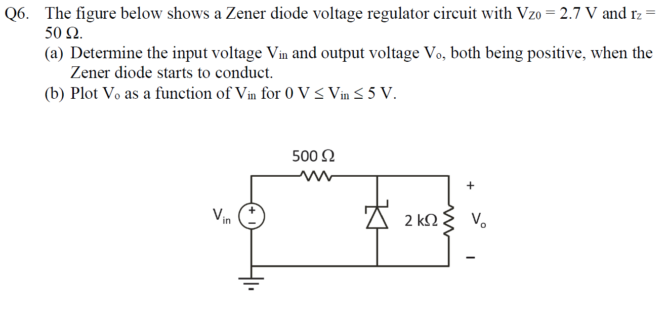
Q6. The figure below shows a Zener diode voltage regulator circuit with Vzo = 2.7 V and rz = 50 12. (a) Determine the input voltage Vin and output voltage Vo, both being positive, when the Zener diode starts to conduct. (b) Plot Vo as a function of Vin for 0 V S Vin 55 V. 500 12 + Vin 2 k92 V.