Page 1 of 1
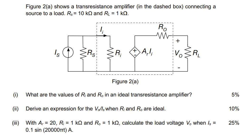
Figure 2(a) shows a transresistance amplifier (in the dashed box) connecting a source to a load. Rs = 10 k and RL = 1 k
Posted: Sun May 15, 2022 4:14 pm
by answerhappygod
- Figure 2 A Shows A Transresistance Amplifier In The Dashed Box Connecting A Source To A Load Rs 10 K And Rl 1 K 1 (96.07 KiB) Viewed 46 times
Figure 2(a) shows a transresistance amplifier (in the dashed box) connecting a source to a load. Rs = 10 k and RL = 1 k 2. R. M + Is SRS ER, A, + 1 VOIR Figure 2(a) (i) What are the values of R; and Ro in an ideal transresistance amplifier? 5% (ii) Derive an expression for the Vds when R; and R. are ideal. 10% 25% (iii) With Ar = 20, R; = 1 kN and R. = 1 k12, calculate the load voltage V. when Is = 0.1 sin (20000nt) A.