Page 1 of 1
Question 1. A schematic of an inverter and its control implementation is shown in the figure. The logical one means that
Posted: Sun May 15, 2022 4:01 pm
by answerhappygod
- Question 1 A Schematic Of An Inverter And Its Control Implementation Is Shown In The Figure The Logical One Means That 1 (144.61 KiB) Viewed 51 times
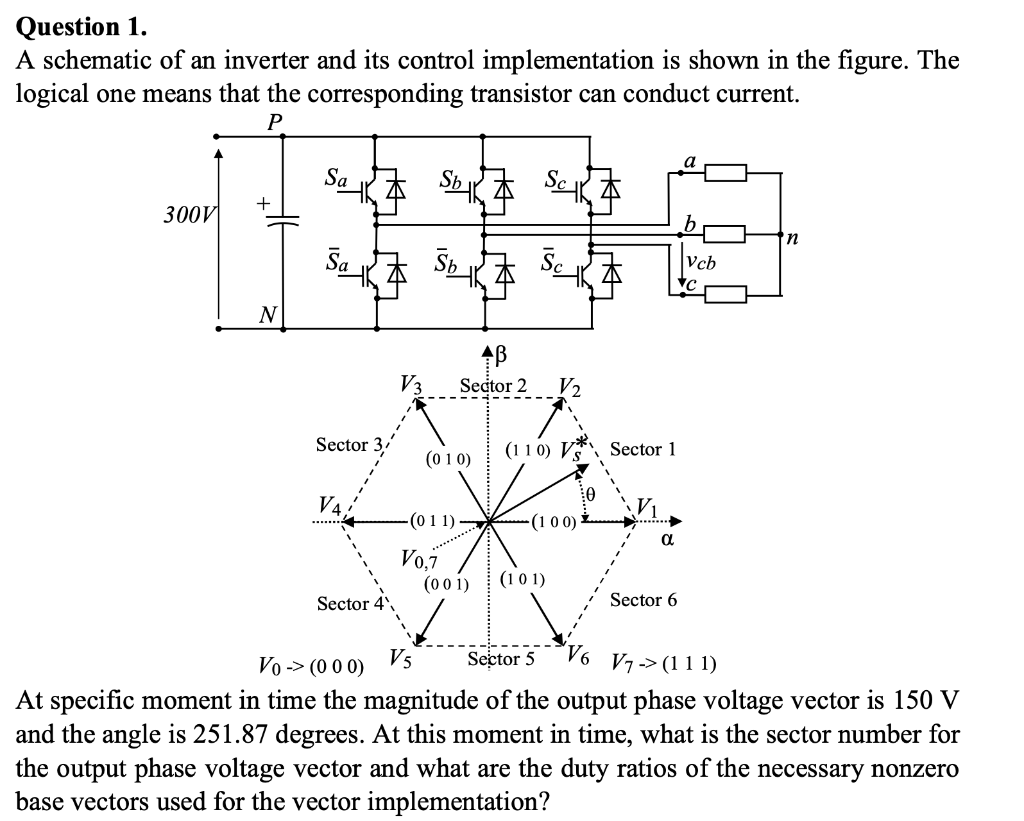
Question 1. A schematic of an inverter and its control implementation is shown in the figure. The logical one means that the corresponding transistor can conduct current. P Sok Sok + 300V b n 本一本 Vcb N AB Sector 2 13 V2 Sector 3 (010) (110) VS Sector 1 V4 -(011) (100) a Voi (001) (101) Sector 4 Sector 6 Vo-> (000) Vs Sector 5 V6 V7-> (111) At specific moment in time the magnitude of the output phase voltage vector is 150 V and the angle is 251.87 degrees. At this moment in time, what is the sector number for the output phase voltage vector and what are the duty ratios of the necessary nonzero base vectors used for the vector implementation?