Page 1 of 1
264 Figure Q.B7a 265 266 267 (b) () In the circuit shown in Figure Q.B7b, the load resistance RLoad is a variable resist
Posted: Sun May 15, 2022 3:56 pm
by answerhappygod
- 264 Figure Q B7a 265 266 267 B In The Circuit Shown In Figure Q B7b The Load Resistance Rload Is A Variable Resist 1 (57.43 KiB) Viewed 55 times
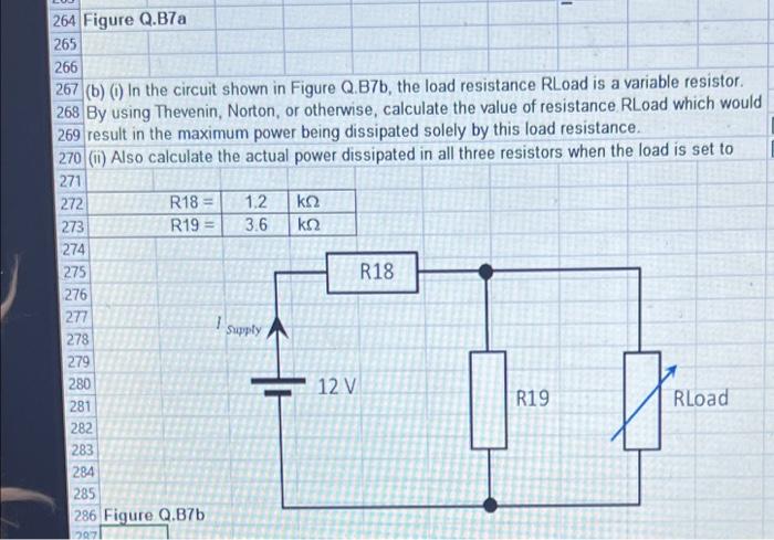
264 Figure Q.B7a 265 266 267 (b) () In the circuit shown in Figure Q.B7b, the load resistance RLoad is a variable resistor. 268 By using Thevenin, Norton, or otherwise, calculate the value of resistance RLoad which would 269 result in the maximum power being dissipated solely by this load resistance, 270) Also calculate the actual power dissipated in all three resistors when the load is set to 271 272 R18 = 1.2 ΚΩ 273 R19 = 3.6 ΚΩ 274 275 R18 276 277 1 278 279 280 12 V R19 Rload 281 282 283 284 285 286 Figure Q.B7b Supply 1071