Page 1 of 1
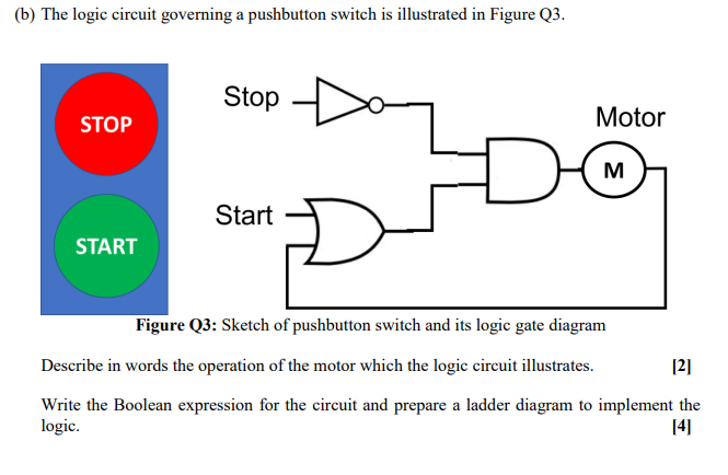
(b) The logic circuit governing a pushbutton switch is illustrated in Figure Q3. Stop STOP Motor M Start START Figure Q3
Posted: Sun May 15, 2022 3:47 pm
by answerhappygod
- B The Logic Circuit Governing A Pushbutton Switch Is Illustrated In Figure Q3 Stop Stop Motor M Start Start Figure Q3 1 (66.8 KiB) Viewed 43 times
(b) The logic circuit governing a pushbutton switch is illustrated in Figure Q3. Stop STOP Motor M Start START Figure Q3: Sketch of pushbutton switch and its logic gate diagram Describe in words the operation of the motor which the logic circuit illustrates. 121 Write the Boolean expression for the circuit and prepare a ladder diagram to implement the logic. 14