Page 1 of 1
(b) Figure 2 shows a block diagram of an AM transmitter. Message signal, 4 kHz Balance Modulator 1 Ceramic BPF Balance M
Posted: Sun May 15, 2022 3:35 pm
by answerhappygod
- B Figure 2 Shows A Block Diagram Of An Am Transmitter Message Signal 4 Khz Balance Modulator 1 Ceramic Bpf Balance M 1 (65.56 KiB) Viewed 48 times
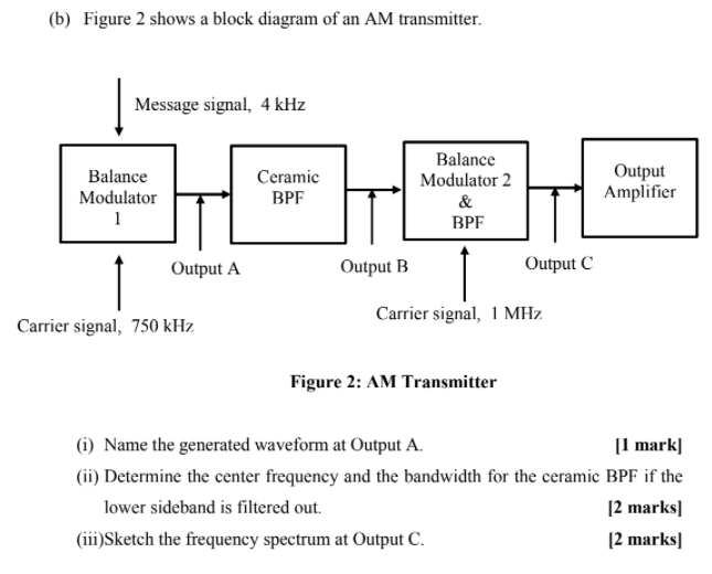
(b) Figure 2 shows a block diagram of an AM transmitter. Message signal, 4 kHz Balance Modulator 1 Ceramic BPF Balance Modulator 2 & BPF Output Amplifier Output A Output B Output C Carrier signal, 750 kHz Carrier signal, 1 MHZ Figure 2: AM Transmitter (1) Name the generated waveform at Output A. [1 mark] (ii) Determine the center frequency and the bandwidth for the ceramic BPF if the lower sideband is filtered out. [2 marks] (iii)Sketch the frequency spectrum at Output C. [2 marks]