Page 1 of 1
a) Figure B2a below shows transmission line 1 (with length 5 m and characteristic impedance Z) joined to transmission li
Posted: Sun May 15, 2022 3:30 pm
by answerhappygod
- A Figure B2a Below Shows Transmission Line 1 With Length 5 M And Characteristic Impedance Z Joined To Transmission Li 1 (44.37 KiB) Viewed 48 times
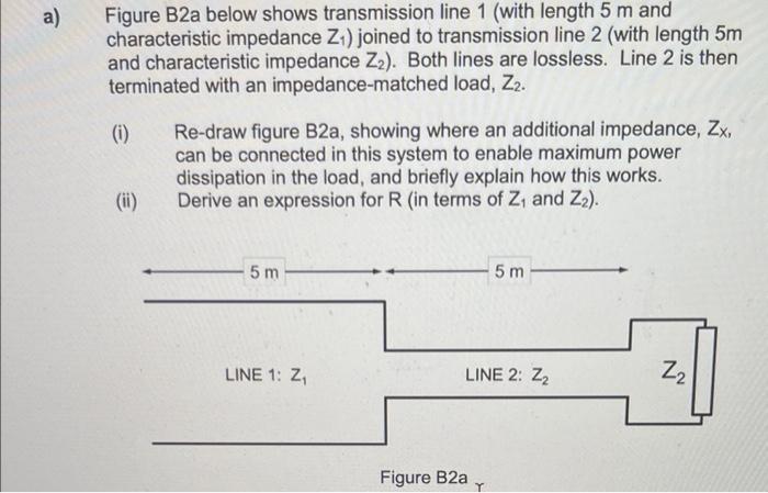
a) Figure B2a below shows transmission line 1 (with length 5 m and characteristic impedance Z) joined to transmission line 2 (with length 5m and characteristic impedance Zz). Both lines are lossless. Line 2 is then terminated with an impedance-matched load, Z2. (0) ( Re-draw figure B2a, showing where an additional impedance, ZX, can be connected in this system to enable maximum power dissipation in the load, and briefly explain how this works. Derive an expression for R (in terms of Z, and Z2). (ii) ( 5 m 5 m LINE 1: Z LINE 2: Z2 Z2 Figure B2a Y