Page 1 of 1
Q4(ii) Discrete-Time System The block diagram that implements a digital system H(2) is shown in Figure 04(b). x[n] y[n]
Posted: Sun May 15, 2022 3:08 pm
by answerhappygod
- Q4 Ii Discrete Time System The Block Diagram That Implements A Digital System H 2 Is Shown In Figure 04 B X N Y N 1 (66.18 KiB) Viewed 53 times
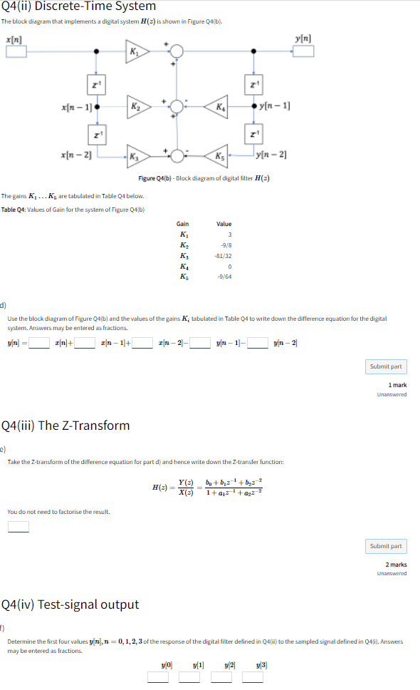
Q4(ii) Discrete-Time System The block diagram that implements a digital system H(2) is shown in Figure 04(b). x[n] y[n] K 21 xn-1] K2 KA y(n-1) Z z! x[n-2] Ks y[n-21 Figure Q4(b) -Block diagram of digital filter H2) The gains K...K, are tabulated in Table 4 below. Table 04: Values of Gain for the system of Figure Q4/b) ) Gain K kg K K K Ks Value 3 -9/8 -81/32 0 0 -9/64 d) d) Use the block diagram of Figure 04(b) and the values of the gains Kitabulated in Table 04 to write down the difference equation for the digital system. Answers may be entered as fractions. yn = In+ ] n-1+ Zn-2 [ (T-1)- yn-21 Submit part 1 mark Unanswered Q4(iii) The Z-Transform e) Take the Z-transform of the difference equation for part d) and hence write down the Z-transfer function: H(2) Y()_0+012-'+byz? (2 bo +22 X(3) 1+212 +agz-? You do not need to factorise the result. Submit part 2 marks Unanswered Q4(iv) Test-signal output 1) Determine the first four valuesyn, n = 0,1,2,3 of the response of the digital filter defined in 04 (ii) to the sampled signal defined in 04li). Answers may be entered as fractions. yo y[1] y2 y3]