Page 1 of 1
Q2: For the system shown in Fig. 2, simulate the voltage waveform given in Fig. 3 considering a three-phase fault occurs
Posted: Sun May 15, 2022 2:45 pm
by answerhappygod
- Q2 For The System Shown In Fig 2 Simulate The Voltage Waveform Given In Fig 3 Considering A Three Phase Fault Occurs 1 (40.5 KiB) Viewed 44 times
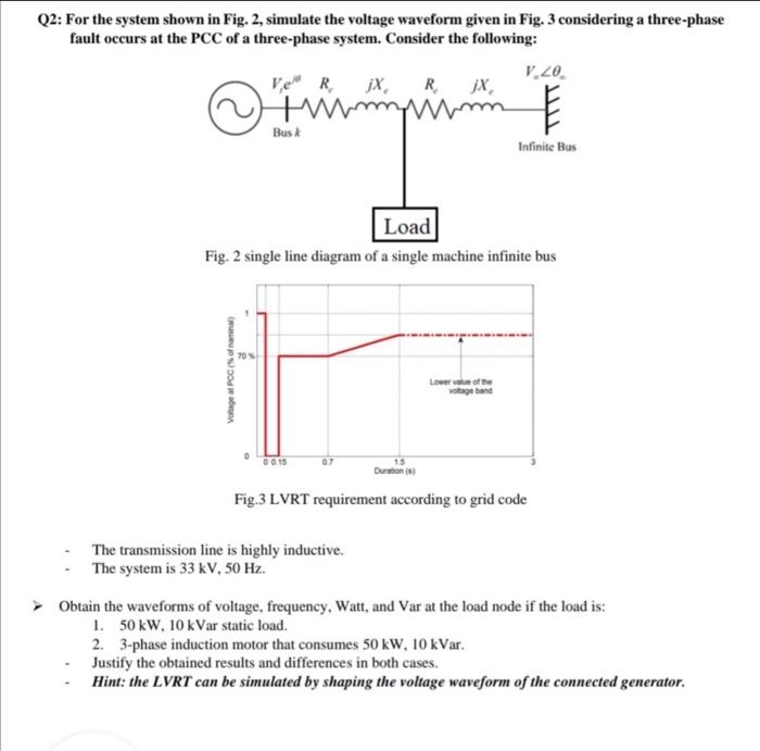
Q2: For the system shown in Fig. 2, simulate the voltage waveform given in Fig. 3 considering a three-phase fault occurs at the PCC of a three-phase system. Consider the following: V.20. Rjx R XX erumpam win Busk Infinite Bus Load Fig. 2 single line diagram of a single machine infinite bus Vortage at Poconomia Lower of the voltage and 0 0.15 07 Duration Fig.3 LVRT requirement according to grid code The transmission line is highly inductive. The system is 33 kV, 50 Hz. Obtain the waveforms of voltage, frequency, Watt, and Var at the load node if the load is: 1. 50kW, 10 kVar static load. 2. 3-phase induction motor that consumes 50 kW, 10 kVar. Justify the obtained results and differences in both cases. Hint: the LVRT can be simulated by shaping the voltage waveform of the connected generator.