Page 1 of 1
Question 1 (25 %) The circuit shown in Figure I has Vps = 5V, R=2 k2, and V,=0.7V. The diode is assumed to be the offset
Posted: Sun May 15, 2022 2:33 pm
by answerhappygod
- Question 1 25 The Circuit Shown In Figure I Has Vps 5v R 2 K2 And V 0 7v The Diode Is Assumed To Be The Offset 1 (35.11 KiB) Viewed 54 times
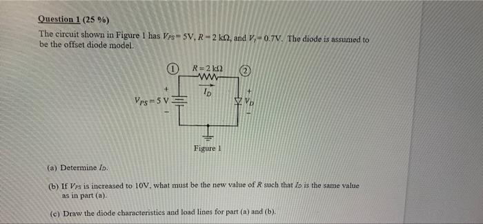
Question 1 (25 %) The circuit shown in Figure I has Vps = 5V, R=2 k2, and V,=0.7V. The diode is assumed to be the offset diode model. R=2 k2 w ID Vps = 5 V V Figure 1 (a) Determine Io. (b) If Vrs is increased to 10V, what must be the new value of Rsuch that Io is the same value as in part (a). (c) Draw the diode characteristics and load lines for part (a) and (b).