Page 1 of 1
CRO Function Generator 15V Ext Tig +o 100k 3. RF Inverting input of the 10k opamp R1 12 Inputs Vout + 6 4 Non Inverting
Posted: Sun May 15, 2022 2:26 pm
by answerhappygod
- Cro Function Generator 15v Ext Tig O 100k 3 Rf Inverting Input Of The 10k Opamp R1 12 Inputs Vout 6 4 Non Inverting 1 (68.83 KiB) Viewed 52 times
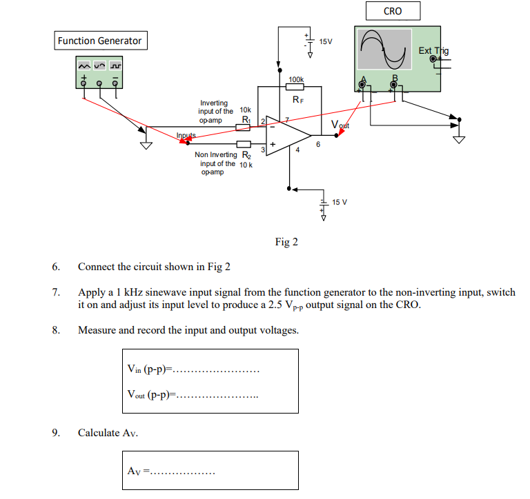
CRO Function Generator 15V Ext Tig +o 100k 3. RF Inverting input of the 10k opamp R1 12 Inputs Vout + 6 4 Non Inverting R input of the 10k opamp 15 V 6. 7. Fig 2 Connect the circuit shown in Fig 2 Apply a 1 kHz sinewave input signal from the function generator to the non-inverting input, switch it on and adjust its input level to produce a 2.5 Vp-p output signal on the CRO. Measure and record the input and output voltages. 8. Vin (p-p... Vout (P-p) 9. Calculate Av. Ay =....
10. Sketch your observations below. Mark which trace is Vin and which is Vout. Channel 1 sensitivity: V/cm Channel 2 sensitivity: V/cm Time base: .................ms/cm