Page 1 of 1
When the following code is executed using the pipeline shown in figure attached: Cycle Instruction 1 N 3 4 01 6 7 add $t
Posted: Sun May 15, 2022 10:09 am
by answerhappygod
- When The Following Code Is Executed Using The Pipeline Shown In Figure Attached Cycle Instruction 1 N 3 4 01 6 7 Add T 1 (76.05 KiB) Viewed 50 times
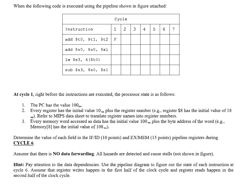
When the following code is executed using the pipeline shown in figure attached: Cycle Instruction 1 N 3 4 01 6 7 add $t0,$t1, $t2 F add $80, $50, $al lw $s3, 4($t0) sub $s3, $80, $sl At cycle 1, right before the instructions are executed, the processor state is as follows: 1. The PC has the value 100 2. Every register has the initial value 10ten plus the register number (e.g., register $8 has the initial value of 18 ten). Refer to MIPS data sheet to translate register names into register numbers. 3. Every memory word accessed as data has the initial value 100 .co plus the byte address of the word (e.g., Memory[8] has the initial value of 108 zen). Determine the value of each field in the IF/ID (10 points) and EX/ MEM (15 points) pipeline registers during CYCLE 6. Assume that there is NO data forwarding. All hazards are detected and cause stalls (not shown in figure). Hint: Pay attention to the data dependencies. Use the pipeline diagram to figure out the state of each instruction at cycle 6. Assume that register writes happen in the first half of the clock cycle and register reads happen in the second half of the clock cycle.