- A Block Diagram Of The Single Cycle Cpu Discussed In Class Is Shown Below Show How To To Set Each Of The Control Signal 1 (192.04 KiB) Viewed 54 times
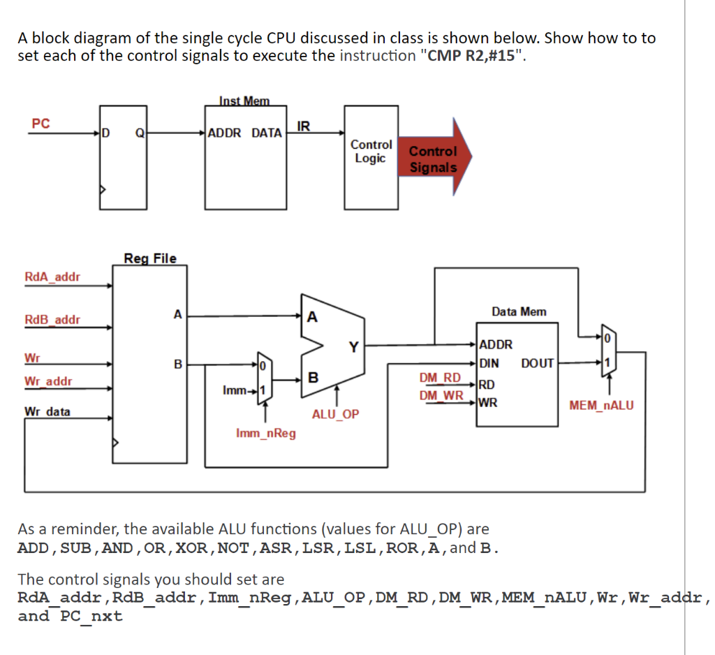
A block diagram of the single cycle CPU discussed in class is shown below. Show how to to set each of the control signals to execute the instruction "CMP R2,#15". Inst Mem PC IR D Q! ADDR DATA Control Logic Control Signals Reg File RdA addr A Data Mem RdB_addr A Y Wr B DOUT ਏ ਤੋਂ ADDR DIN DM RD RD DM WR WR Wr addr B Imm-1 Wr data MEM_NALU ALU_OP Imm_nReg As a reminder, the available ALU functions (values for ALU_OP) are ADD, SUB, AND, OR, XOR, NOT, ASR, LSR, LSL , ROR, A, and B. 1 The control signals you should set are RdA_addr , RdB_addr, Imm_nReg , ALU_OP, DM_RD, DM_WR, MEM_nALU, Wr, Wr_addr, and PC_nxt 1