Page 1 of 1
Use the information below to answer the following questions: In the simple AC circuit shown on the right, C = 0.031 F L
Posted: Mon May 09, 2022 2:08 pm
by answerhappygod
- Use The Information Below To Answer The Following Questions In The Simple Ac Circuit Shown On The Right C 0 031 F L 1 (75.74 KiB) Viewed 27 times
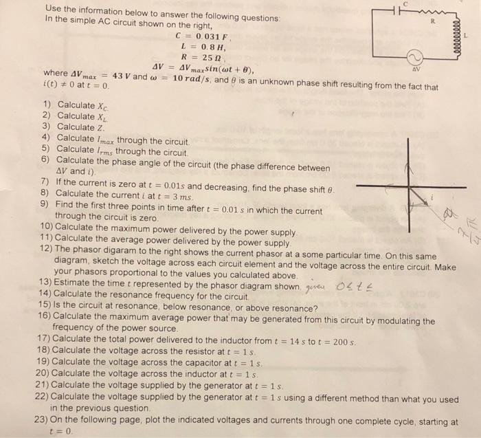
Use the information below to answer the following questions: In the simple AC circuit shown on the right, C = 0.031 F L = 0.8 H, R = 251 AV = AV marsin(wt+), where AV = 43 V and w = 10 rad/s, and is an unknown phase shift resulting from the fact that i(t) = 0 at t = 0. Queelle AV mex 1) Calculate Xc. 2) Calculate X 3) Calculate z 4) Calculate Imar through the circuit 5) Calculate Irms through the circuit 6) Calculate the phase angle of the circuit (the phase difference between AV and t) 7) If the current is zero at t = 0.01s and decreasing, find the phase shifte 8) Calculate the current i at t = 3 ms. 9) Find the first three points in time after t = 0.01 s in which the current through the circuit is zero. 10) Calculate the maximum power delivered by the power supply 11) Calculate the average power delivered by the power supply 12) The phasor digaram to the right shows the current phasor at a some particular time. On this same diagram, sketch the voltage across each circuit element and the voltage across the entire circuit. Make your phasors proportional to the values you calculated above 13) Estimate the time t represented by the phasor diagram shown given oste 14) Calculate the resonance frequency for the circuit 15) Is the circuit at resonance, below resonance, or above resonance? 16) Calculate the maximum average power that may be generated from this circuit by modulating the frequency of the power source. 17) Calculate the total power delivered to the inductor from t = 14 s to t = 200 s. 18) Calculate the voltage across the resistor at t = 15 19) Calculate the voltage across the capacitor at t = 15. 20) Calculate the voltage across the inductor at t = 1 s. 21) Calculate the voltage supplied by the generator at t = 15. 22) Calculate the voltage supplied by the generator at t = 1 s using a different method than what you used in the previous question 23) On the following page, plot the indicated voltages and currents through one complete cycle, starting at L=0