Page 1 of 1
Problem #4 The figure below shows a series LRC circuit with R = 100.0 2, L = 200.0 mH, and C= 300.0 uF, connected to a p
Posted: Mon May 09, 2022 1:56 pm
by answerhappygod
- Problem 4 The Figure Below Shows A Series Lrc Circuit With R 100 0 2 L 200 0 Mh And C 300 0 Uf Connected To A P 1 (63.04 KiB) Viewed 22 times
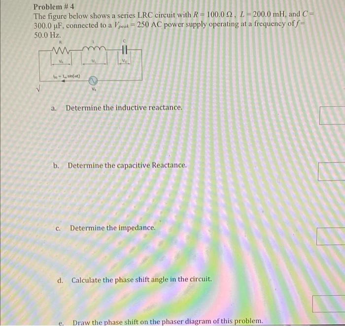
Problem #4 The figure below shows a series LRC circuit with R = 100.0 2, L = 200.0 mH, and C= 300.0 uF, connected to a peak = 250 AC power supply operating at a frequency of S= 50.0 Hz. 11 -net) V V. a. Determine the inductive reactance. b. Determine the capacitive Reactance. c. Determine the impedance. d. Calculate the phase shift angle in the circuit. e. Draw the phase shift on the phaser diagram of this problem.