Page 1 of 1
SIMULATION: Construct each of the three circuits implemented in 1) using SPICE. Select Vod=5V (logic 1) and ground=0V (l
Posted: Mon May 09, 2022 1:49 pm
by answerhappygod
- Simulation Construct Each Of The Three Circuits Implemented In 1 Using Spice Select Vod 5v Logic 1 And Ground 0v L 1 (148.2 KiB) Viewed 27 times
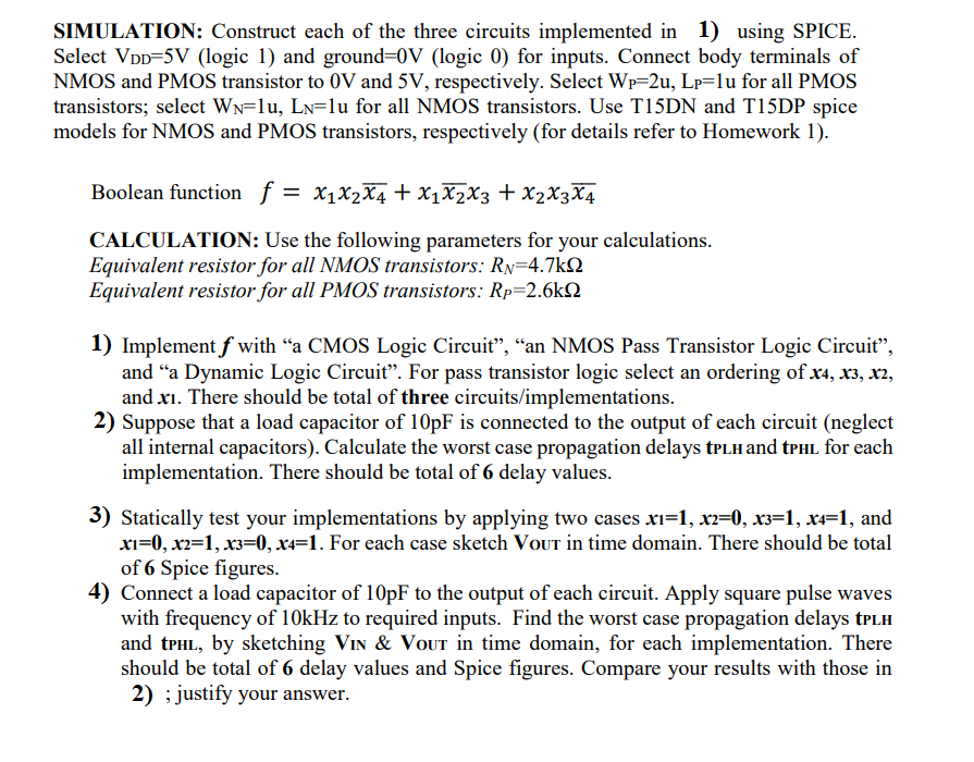
SIMULATION: Construct each of the three circuits implemented in 1) using SPICE. Select Vod=5V (logic 1) and ground=0V (logic 0) for inputs. Connect body terminals of NMOS and PMOS transistor to 0V and 5V, respectively. Select Wp=2u, Lp=lu for all PMOS transistors; select Ww=lu, Ln=lu for all NMOS transistors. Use T15DN and T15DP spice models for NMOS and PMOS transistors, respectively (for details refer to Homework 1). Boolean function = X1X2X4 + x1x2x3 + x2x3X4 CALCULATION: Use the following parameters for your calculations. Equivalent resistor for all NMOS transistors: Rp=4.7k12 Equivalent resistor for all PMOS transistors: Rp=2.6k12 1) Implement f with “a CMOS Logic Circuit”, “an NMOS Pass Transistor Logic Circuit”, and “a Dynamic Logic Circuit”. For pass transistor logic select an ordering of x4, X3, X2, and xi. There should be total of three circuits/implementations. 2) Suppose that a load capacitor of 10pF is connected to the output of each circuit (neglect all internal capacitors). Calculate the worst case propagation delays tplh and tphl for each implementation. There should be total of 6 delay values. 3) Statically test your implementations by applying two cases x1=1, x2=0, x3=1, x4=1, and xi=0, x2=1, x3=0, x4=1. For each case sketch Vout in time domain. There should be total of 6 Spice figures. 4) Connect a load capacitor of 10pF to the output of each circuit. Apply square pulse waves with frequency of 10kHz to required inputs. Find the worst case propagation delays tell and tphl, by sketching Vin & Vout in time domain, for each implementation. There should be total of 6 delay values and Spice figures. Compare your results with those in 2) ; justify your answer.